Can You Use a Gaming Laptop for Work and School?

A high-performance gaming laptop for work and school set up on a clean wooden desk next to engineering notes.

Many students and professionals wonder if a gaming laptop for work and school can replace a traditional business ultrabook. Traditionally, people view gaming rigs as loud, heavy machines built solely for entertainment. However, modern technology bridges this gap completely. Today, buying a versatile machine gives you incredible processing power for both professional tasks and intensive gaming sessions.

Why a Gaming Laptop for Work and School Delivers Raw Power

Underneath the hood, these machines pack serious hardware. Manufacturers equip them with multi-core processors, dedicated graphics cards, and ultra-fast NVMe storage drives. Consequently, these components excel at heavy workloads.

For example, civil engineers, video editors, and programmers push their systems hard with demanding applications like AutoCAD, Adobe Premiere Pro, or heavy compiling software. A standard office laptop often stutters under these loads, whereas a high-performance machine handles complex 3D rendering and video encoding smoothly without breaking a sweat.

Navigating the Aesthetic Trade-Off

Despite their incredible speed, these systems come with distinct visual differences. Manufacturers often style gaming rigs with aggressive angles, colorful RGB keyboards, and bulkier chassis designs. Therefore, walking into a corporate boardroom or a quiet university lecture hall with a flashing neon machine might feel slightly out of place.

Fortunately, many modern brands now offer “stealth” gaming models. These newer designs feature sleek, matte-black finishes that blend professionally into any workspace while retaining powerful internal components.

Understanding Battery Realities and Portability

Another crucial factor involves battery life. Because these devices power high-end graphics chips and intense processors, they consume energy very quickly. Consequently, you will likely need to carry your charger wherever you go.

While standard ultrabooks easily last a full workday on a single charge, a heavy-duty rig typically lasts only a few hours under continuous workloads. Therefore, you must always plan your workspace around available power outlets when working remotely.

Making Your Final Hardware Decision

Ultimately, choosing a gaming laptop for work and school depends entirely on your daily priorities. If you value raw computing power for engineering tasks, coding, or video production above lightweight portability, this hardware choice serves you exceptionally well. For further reading and in-depth hardware reviews, you can visit PCMag Laptop Guides.

References

  1. Tom’s Hardware. (2026). Gaming Laptops vs. Workstations: Performance and Productivity Benchmarks.
  2. PCWorld. (2025). Evaluating Portability and Battery Life in Modern High-Performance Laptops.

 Gaming Laptop Upgradeability: Can You Upgrade RAM and Storage Later?

Gaming Laptop Upgradeability: Can You Upgrade RAM and Storage Later?

Many computer buyers wonder whether they can enhance their systems after purchase. Evaluating gaming laptop upgradeability helps you plan for long-term device ownership and future-proofing. Technology changes rapidly, and software demands increase every year. Therefore, understanding whether you can swap components later saves you money and extends your hardware’s lifespan.

Modular vs. Soldered Design in Gaming Laptop Upgradeability

 A technician reviewing gaming laptop upgradeability components like RAM and NVMe storage slots.

When examining gaming laptop upgradeability, you must first understand internal layouts. Traditional gaming laptops often feature removable bottom panels and socketed parts for easy upgrades. Conversely, modern thin-and-light models frequently solder components directly to the motherboard.

Consequently, soldered memory cannot be removed or replaced later. Always verify internal build types before buying a slim chassis if you plan to modify your system in the future.

Storage Expansion and NVMe Slots

Fortunately, many customizable rigs still prioritize storage flexibility. Manufacturers often include a second NVMe SSD slot in upgradeable models. Therefore, you can easily insert an extra drive when your game library grows.

Adding storage requires only a screwdriver and a few minutes of your time. This simple upgrade prevents you from deleting important files or reinstalling massive operating systems as your storage needs expand.

The “Buy It Right” Rule for Hardware Purchases

Because component restrictions vary widely, you should always follow the golden rule of hardware purchasing. Before making any financial commitment, check user manuals, teardown guides, or professional reviews regarding gaming laptop upgradeability.

Manufacturers often publish detailed service guides online. Checking these resources ensures you never buy a locked-down machine expecting easy modifications later.

Planning for future maintenance guarantees your machine stays relevant for years. By prioritizing modular designs, you protect your investment against growing software requirements. Ultimately, checking component flexibility before purchase brings complete peace of mind. For more hardware maintenance tips and comprehensive guides, you can visit Tom’s Hardware.

References

  1. iFixit. (2025). Laptop Repairability and Modular Design Standards.
  2. LaptopMag. (2026). Upgrading RAM and NVMe SSDs in Modern Portable Rigs.

Step-by-Step Guide to Calculating Steel Reinforcement in Concrete Slabs

When you design reinforced concrete structures, calculating steel reinforcement in concrete slabs remains a critical task. Concrete handles high compressive loads easily, but it struggles with tension forces. Therefore, civil engineers integrate steel bars to absorb tensile stresses. You must understand the core engineering principles and mathematical formulas to ensure your slabs remain safe and durable over time.

Estimating Bending Moments When Calculating Steel Reinforcement in Concrete Slabs

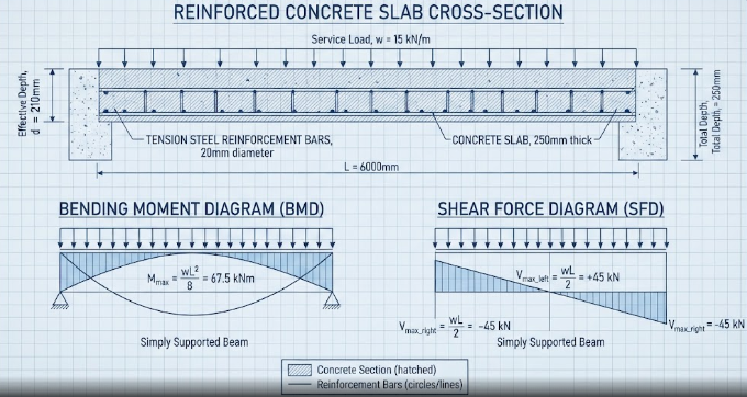
Before you compute any steel area, you must determine the bending moments acting on the slab. Engineers derive these bending moments from factored loads and effective spans. Specifically, dead loads and live loads combine to form ultimate design loads.

You can apply structural coefficients for continuous slabs or use classic bending moment formulas from structural analysis codes. For instance, a simply supported one-way slab uses the standard moment formula M = (w * l^2) / 8. Consequently, this value sets the foundation for your subsequent steel design calculations.

Determining the Required Area of Steel

After you establish the maximum bending moment, you can calculate the required cross-sectional area of tension reinforcement (As). This step links the ultimate bending moment directly with concrete compressive strength and steel yield strength. Modern design standards use a rectangular stress block to simplify this relationship.

For example, you apply the fundamental equation As = M / (0.87 * fy * z). In this equation, M represents the design bending moment, fy denotes the characteristic strength of the steel reinforcement, and z stands for the lever arm. Furthermore, you must verify that your calculated steel area meets minimum code requirements to prevent sudden brittle failures.

Bar Spacing and Selection Guidelines

Once you know the required steel area, you choose standard bar diameters and check clear spacing limits. Proper bar selection ensures your concrete consolidates fully around the reinforcement without honeycombing. Additionally, adequate spacing maintains strong bond strength between the steel and the surrounding concrete matrix.

You should select bar sizes that match your design calculations while keeping practical construction constraints in mind. For example, you might choose 12mm bars spaced at 150mm intervals. Moreover, always check that your chosen spacing does not exceed maximum limits specified by structural design codes, which usually restrict spacing to prevent wide surface cracks.

Conclusion and Further Engineering Practice

Mastering these foundational design steps allows you to approach any slab project with absolute confidence. By accurately estimating bending moments, calculating steel areas, and selecting proper bar spacings, you guarantee structural safety. To dive deeper into advanced structural design methodologies, you can explore detailed resources at The Structural Guide.

References

  • British Standards Institution. (1997). BS 8110-1: Structural use of concrete – Code of practice for design and construction. BSI London.
  • American Concrete Institute. (2014). Building Code Requirements for Structural Concrete (ACI 318-14). ACI Farmington Hills.
  • Mosley, W. H., Bungey, J. H., & Hulse, R. (2012). Reinforced Concrete Design to Eurocode 2. Palgrave Macmillan.

 Step-by-Step Guide to Determining Dead and Live Loads on Concrete Floor Slabs

dead and live load on reinforced concrete slab

When you design modern buildings, determining dead and live loads on concrete floor slabs remains an essential step for structural stability. You must accurately calculate these forces before any construction begins. Buildings experience various weights daily, and structural engineers must account for every single pound to prevent structural failures. Therefore, mastering this process protects both the building and its occupants.

Calculating Dead Loads When Determining Dead and Live Loads on Concrete Floor Slabs

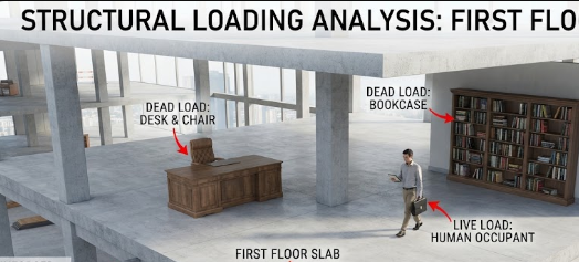
Dead loads represent the permanent, static weights of the structure itself. Specifically, you compute the self-weight of the concrete slab by multiplying its density by its thickness (Self-weight = density * thickness). For instance, reinforced concrete typically weighs about twenty-four kilonewtons per cubic meter.

Additionally, you must add allowances for floor finishes, screed, tiles, ceilings, and internal partitions. These elements add fixed weight that remains constant throughout the entire lifespan of the building.

Selecting Live Loads While Determining Dead and Live Loads on Concrete Floor Slabs

Live loads change over time and depend heavily on how people use the building. Therefore, occupancy type dictates the minimum characteristic imposed loads based on standard building codes. For example, residential rooms require lower live load values than crowded office spaces or heavy storage areas.

You must check local building codes to find exact figures for your specific project. Consequently, proper live load selection ensures your floor handles daily human activity safely.

Applying Load Combinations for Ultimate Limit State

After you calculate individual loads, you must combine them safely using ultimate limit state factors. Ultimate limit state design ensures that structures withstand worst-case loading scenarios without collapsing. Engineers apply specific safety factors to both dead and live loads (Ultimate Load = (1.4 * Dead Load) + (1.6 * Live Load)).

For instance, a common combination multiplies dead loads by one point four and live loads by one point six. These safety margins account for unexpected overloads and material variations.

Solved Example: Calculating Slab Ultimate Load According to BS 8110

Let us examine a practical example to clarify these concepts. Suppose you want to design a concrete floor slab with a span of 5 meters and a thickness of 200mm (0.2 meters). The additional dead load from finishes is 1.2 kN/m², and the live load is 1.5 kN/m². Furthermore, the unit weight of reinforced concrete is 24 kN/m³.

First, you calculate the self-weight of the slab (Self-weight = 24 kN/m^3 * 0.2 m = 4.8 kN/m^2). Next, you find the total dead load by adding the self-weight and the additional dead load (Total Dead Load = 4.8 + 1.2 = 6.0 kN/m^2).

After that, you apply the BS 8110 safety factors for the ultimate limit state (Ultimate Load = (1.4 * 6.0) + (1.6 * 1.5)). Multiplying these values gives 8.4 + 2.4, resulting in an ultimate design load of 10.8 kN/m². Although the 5-meter span is not used directly in calculating the load per square meter, you will need it later when computing bending moments.

Mastering these foundational steps ensures your concrete floor slabs remain safe and reliable. You can easily protect your structures from unexpected failures by carefully calculating every load component. To explore more technical guides and civil engineering resources, you can visit the Civil Engineering Portal.

References

  • American Concrete Institute. (2014). Building Code Requirements for Structural Concrete (ACI 318-14). ACI Farmington Hills.
  • British Standards Institution. (1997). BS 8110-1: Structural use of concrete – Code of practice for design and construction. BSI London.

How to Calculate the Thickness of a Concrete Slab

structural drawing showing slab thickness

When you design floors or roofs, how to calculate the thickness of a concrete slab stands out as a critical task. Therefore, getting this dimension right ensures safety, structural integrity, and cost-effectiveness. Furthermore, an incorrect thickness leads to structural failure or unnecessary expenses. Consequently, every engineer must master the foundational rules governing slab design according to established codes like BS 8110.

Understanding Span-to-Depth Ratios

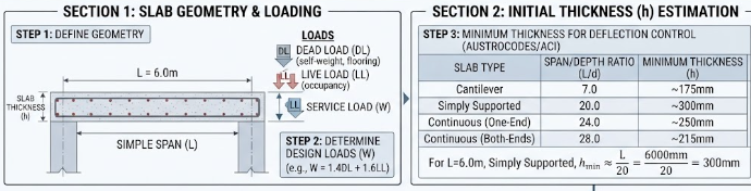
Standards like BS 8110 provide basic guidelines for how to calculate the thickness of a concrete slab. Specifically, structural engineers rely on span-to-effective-depth ratios. For instance, a simply supported slab requires a basic ratio of 20. When you apply a modification factor based on reinforcement stress, you adjust this baseline ratio to control deflection and prevent cracking.

Design Example: Step-by-Breast Calculation

Let us apply a practical example to demonstrate how to calculate the thickness of a concrete slab using BS 8110 guidelines. Assume you have a simply supported slab with a span of 5 m (5000 mm). The additional dead load is 1.2 kN/m2, and the live load is 1.5 kN/m2. Use an ultimate load combination of 1.4gk + 1.6qk, a concrete strength (fcu) of 25 N/mm2, steel yield strength (fy) of 460 N/mm2, a nominal cover of 20 mm, a reinforcement bar diameter of 12 mm, and a modification factor of 1.4.

Computing Effective Depth and Total Thickness

First, determine the allowable span-to-effective-depth ratio by multiplying the basic ratio by the modification factor: 20 x 1.4 = 28.

Next, calculate the required effective depth (d) by dividing the clear span by the allowable ratio: d = 5000 mm / 28 = 178.57 mm.

Finally, find the total slab thickness (h) by adding the effective depth, the nominal cover, and half of the reinforcement bar diameter: h = 178.57 mm + 20 mm + (12 mm / 2) = 204.57 mm. You can round this value up to 210 mm for practical site construction.

Load and Deflection Considerations

Anticipated loads play a massive role in determining structural dimensions. Specifically, you must account for dead loads, such as self-weight, and live loads like furniture and people. Furthermore, ultimate load combinations govern the ultimate limit state checks. If a slab is too thin, it will deflect excessively under heavy service loads. Therefore, engineers calculate deflections carefully to satisfy serviceability requirements.

Durability and Fire Ratings

Structural safety goes beyond simple load-bearing capacity. Environmental exposure classes and fire resistance requirements often force engineers to increase nominal slab thickness. For example, a slab exposed to moisture needs extra concrete cover to protect internal steel reinforcement from corrosion. Additionally, building codes mandate specific minimum thicknesses to achieve required fire resistance ratings. Therefore, even if a thin slab satisfies basic span-to-depth ratios, you must check durability rules.

Conclusion

Mastering how to calculate the thickness of a concrete slab protects buildings from premature failure and costly repairs. By carefully combining span-to-depth ratios, load analysis, and durability codes, you produce safe, reliable structures. For more deep dives into structural design principles, check out The Concrete Society for further reading.

References

  • British Standards Institution. BS 8110-1: Structural use of concrete – Code of practice for design and construction.
  • Mosley, W., Bungey, J., & Hulse, R. (2012). Reinforced Concrete Design. Palgrave Macmillan.

Main Reinforcement vs Distribution Reinforcement in Slab Design

reinforced concrete slanb under construction

When you design concrete floor systems, understanding main reinforcement vs distribution reinforcement is crucial for structural integrity. Concrete handles compression well, but it cracks easily under tension. Therefore, structural engineers place steel bars inside the concrete to carry these tensile loads. However, not all steel bars perform the same function. You must use different types of reinforcement to handle various stresses safely.

Understanding Main Reinforcement vs Distribution Reinforcement in Slabs

The main reinforcement plays the most important structural role in any slab design. Specifically, these primary bars run parallel to the direction of the main bending moment. When loads push down on a slab, the bottom fibers stretch and experience heavy tensile stress.

Consequently, main reinforcement bars absorb these principal tensile stresses and prevent the concrete from cracking or failing. For example, in a simply supported one-way slab, you place the main bars running across the shorter span where bending moments reach their peak. You calculate the exact size and spacing of these bars based on maximum design bending moments.

The Role of Distribution Reinforcement

While main bars handle primary bending, secondary bars manage other critical forces. Distribution reinforcement runs perpendicular to the main reinforcement across the slab. This secondary steel grid serves several vital purposes in structural engineering.

First, it handles transverse stresses that develop across the slab. Second, it helps distribute concentrated or point loads evenly across a wider area. Third, distribution bars resist thermal movements and shrinkage cracking as the concrete cures and hardens over time. For instance, when hot weather causes concrete to shrink, these perpendicular bars hold the matrix together and minimize surface cracking.

Placement Rules and Structural Positioning

Proper placement of your steel bars directly impacts the load-bearing capacity of your slab. Therefore, you must follow strict positioning rules when laying out your structural grid. In a single-layer or multi-layer mesh, you place the main reinforcement outermost to maximize the effective depth of the slab.

The effective depth represents the distance from the extreme compression fiber to the centroid of the tension steel. Placing main bars closer to the outer tension face increases their leverage against bending moments. Meanwhile, you position the distribution reinforcement directly on top of or tied inside the main bars. This arrangement locks the entire steel skeleton in place before you pour fresh concrete.

Conclusion

Mastering the balance between primary and secondary steel bars ensures your concrete structures remain safe and durable. By understanding the distinct functions of each steel layer, you can design slabs that resist bending, control cracks, and handle heavy loads efficiently. To explore more construction tutorials and general engineering insights, you can visit Specs Finder.

References

  • British Standards Institution. (1997). BS 8110-1: Structural use of concrete – Code of practice for design and construction. BSI London.
  • American Concrete Institute. (2014). Building Code Requirements for Structural Concrete (ACI 318-14). ACI Farmington Hills.
  • Mosley, W. H., Bungey, J. H., & Hulse, R. (2012). Reinforced Concrete Design to Eurocode 2. Palgrave Macmillan.