In 2026, soaring cement prices place a massive financial burden on self-builders and property developers across Africa. Consequently, engineers and builders actively seek cost-effective structural solutions. Today, Compressed Earth Bricks trend heavily as a premium, load-bearing alternative for modern construction projects. You must understand that these blocks differ entirely from traditional, fragile mud bricks. Builders use mechanical presses to turn local soil into highly durable building units. Therefore, they offer superior structural integrity and financial savings compared to standard sand-crete blocks. In this article, we will explore the technical specifications that make these earth blocks an excellent choice for your site.
The Stabilization Spec Ratio for Compressed Earth Bricks
Many people still confuse modern earth building with old-school mud huts. However, modern Compressed Earth Bricks use a precise stabilization spec ratio to ensure longevity. Engineers mix local laterite soil with just 5% to 8% Portland cement or lime. Afterward, they mechanically compress the mixture to remove air pockets and maximize density. Because builders only need a tiny fraction of cement, this method drastically reduces the total structural cost.
For example, if you build a standard three-bedroom house, this 5% ratio saves you millions of Naira on cement purchases. Furthermore, this small addition of a chemical stabilizer permanently binds the soil particles together. Thus, water cannot wash the walls away, even during intense tropical rainstorms.
Compressive Strength Benchmarks of Compressed Earth Bricks
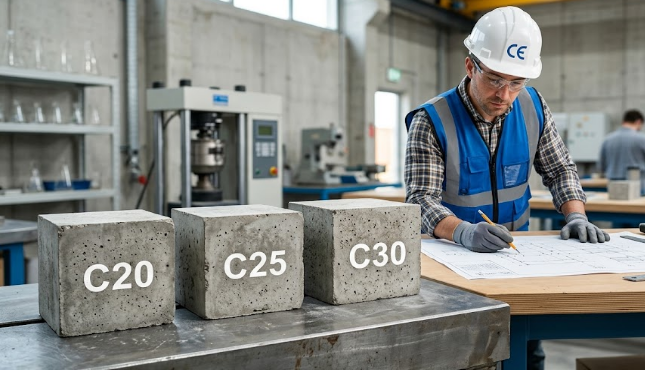
When you design a load-bearing wall, you need materials that can safely support the roof and concrete floors. Therefore, we must look at the hard engineering data. A properly cured batch of Compressed Earth Bricks achieves a compressive strength ranging from 4.0 to 7.0 MPa. Interestingly, this impressive number easily meets, and often exceeds, the 3.5 MPa regulatory standard required for standard residential sand-crete blocks.
Consequently, you can confidently use these stabilized earth blocks for single or double-story buildings without worrying about structural failure. Moreover, because heavy machines compress the soil so tightly, these blocks resist cracking far better than traditional hollow blocks. Builders consistently report fewer breakages during transport and handling on the construction site.
Thermal Mass Advantages of Compressed Earth Bricks
Beyond structural strength, Compressed Earth Bricks provide an incredible indoor climate advantage. These solid, dense walls feature massive thermal inertia. Specifically, they absorb the intense midday tropical heat instead of letting it pass directly into the living spaces. Later, the walls slowly release this stored heat at night when the outside air cools down.
As a result, the bricks naturally maintain an indoor temperature that remains 3°C to 5°C cooler than the outside environment. Therefore, homeowners stay perfectly comfortable without running expensive air conditioning hardware all day. Ultimately, this natural insulation lowers long-term electricity bills significantly while keeping the home perfectly cool and well-ventilated.
The Interlocking Dry-Stack Build System
Finally, the modern interlocking design completely revolutionizes how masons assemble structural walls. Compressed Earth Bricks often feature engineered male and female grooves that fit together securely, much like Lego pieces. Because of this precise fit, masons require zero mortar layers between the horizontal joints during wall construction.
Consequently, this innovative dry-stack system cuts labor time by a massive 40%. Additionally, the interlocking system creates a beautifully smooth, aligned surface on both sides of the wall. Therefore, you completely eliminate the need for expensive external plastering and rendering. The builder simply applies a clear water-repellent sealant to protect and highlight the beautiful natural earth finish.
Conclusion
In conclusion, Compressed Earth Bricks offer an unbeatable combination of structural strength, massive cost savings, and advanced thermal comfort. By switching to this modern building method, you protect your budget from unpredictable cement costs while delivering a superior, eco-friendly building. As civil engineering practices continue to evolve in Africa, adopting smart, locally sourced materials becomes absolutely necessary for sustainable development. If you want to learn more about the exact soil testing procedures for stabilizing earth blocks, you can explore further reading at the Practical Action engineering resources page.
References
- Guillaud, H., Joffroy, T., & Odul, P. (1995). Compressed Earth Blocks: Manual of Design and Construction. Vieweg.
- Adam, E. A., & Agib, A. R. A. (2001). Compressed Earth Block Manufacture. United Nations Industrial Development Organization (UNIDO).