Modern data centers face a massive challenge when handling workloads like artificial intelligence and big data analytics. Standard servers often run out of memory quickly, which forces operators to buy more physical hardware than they actually need. To solve this problem, engineers developed CXL 3.1: The Specs Unifying Server Motherboard Memory. This breakthrough standard changes how we think about resource allocation by breaking down physical barriers between individual servers.
What is CXL 3.1 and How Does It Work?
Compute Express Link (CXL) is an open industry standard that creates a high-speed connection between processors and external devices. Specifically, the CXL 3.1 version runs directly over the physical layer of PCI Express (PCIe) Gen 6. Consequently, it achieves double the bandwidth of previous generations while using the exact same physical slots on a motherboard.
By using this advanced connection, processors (CPUs), graphics cards (GPUs), and specialized smart accelerators can share a single, unified pool of memory. The system maintains “coherency” across the board. This means that if a GPU changes a piece of data in the shared pool, the CPU sees that exact change instantly. As a result, different chips can work on the same task together without waiting for slow data transfers.
Understanding the CXL 3.1 Architecture
The standard works by combining three distinct protocols over a single physical link:
- CXL.io: This protocol handles device discovery, configuration, and register access. It works exactly like standard PCIe.
- CXL.cache: This protocol allows peripheral devices, such as GPUs, to efficiently access and cache the host system’s memory.
- CXL.mem: This protocol lets the host CPU access memory attached to an external CXL device as if it were a standard local motherboard DIMM.
By combining these protocols, CXL 3.1 makes external, chassis-mounted memory modules look and feel like local RAM to the server operating system.
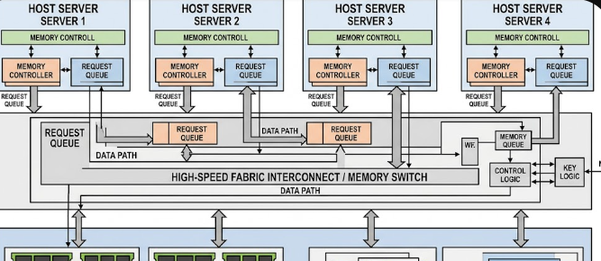
Fabric Management and Multi-Head Devices
In a traditional setup, you cannot share a single stick of RAM between two separate motherboards. However, the new fabric management specifications in CXL 3.1 change this reality entirely. The system uses “Multi-Head” devices that can plug into multiple host server nodes at the exact same time.
Because of this multi-head capability, a central fabric manager can assign specific blocks of RAM to different servers on-the-fly. For example, if Server A suddenly experiences a massive traffic spike, the manager instantly routes extra gigabytes of RAM to it. This entire process happens electronically in real-time. Therefore, you do not need to shut down the server, open the chassis, or reboot the operating system to upgrade memory.
Direct Memory Access Latency Floors
Many administrators worry that moving memory outside of the motherboard will slow down performance. Fortunately, CXL 3.1 solves this concern by keeping transport latency extremely low. Because the protocol bypasses traditional complex network layers, it keeps extra latency down to single-digit nanoseconds.
To put this in perspective, look at the comparison table below:
| Memory Connection Type | Relative Latency Overhead | Performance Class |
| On-Board DDR5 DIMM | Baseline (0 ns) | Native / Fastest |
| CXL 3.1 External Pool | +10 to +15 ns | Near-Native |
| Standard RDMA Network | +1,000 to +5,000 ns | Delayed / Slow |
This tiny latency penalty means that fabric-attached memory banks perform almost identically to traditional on-board RAM. Consequently, applications run smoothly without bottlenecking.
Real-World Data Center Efficiency
From a business perspective, memory pooling solves one of the biggest money-wasting issues in IT: “stranded memory.” In typical data centers, one server might use 90% of its CPU but only 10% of its RAM. That leftover RAM sits idle and cannot be used by any other machine.
By utilizing CXL 3.1, companies can pool all their memory together in a central chassis. When a server needs memory, it borrows it from the shared pool. Once the task is complete, the server returns the memory back to the pool. This dynamic sharing slashes total operational hardware costs because companies no longer need to over-provision their physical servers.
For a deeper dive into the technical details and upcoming hardware releases of this standard, you can explore the official technical documentation on the CXL Consortium Website.
References
- Compute Express Link (CXL) Consortium. (2023). CXL 3.1 Specification.
- PCI-SIG. (2022). PCI Express Base Specification Revision 6.0.
- Rambus Technical Blog. (2024). Understanding CXL Memory Pooling and Latency.