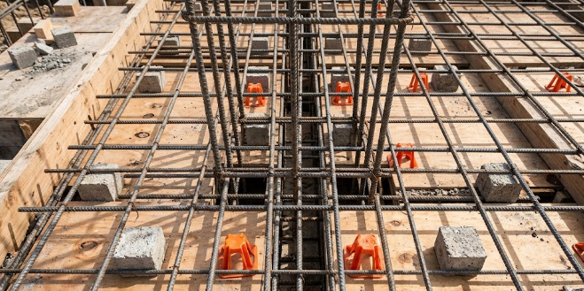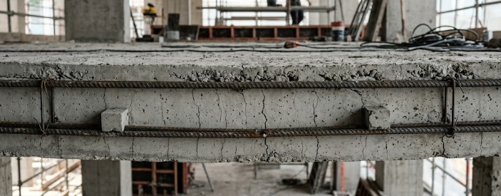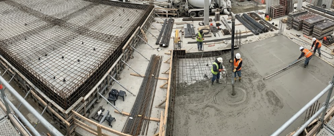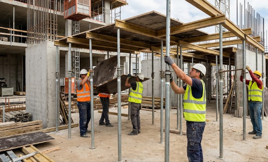
Are you curious about how modern buildings stay strong and stable? Understanding reinforced concrete slabs is essential because these horizontal structural elements form the floors and roofs we use every day. Without them, multi-story buildings and safe roofing systems would not exist in modern construction. Builders rely on these components to create flat, sturdy surfaces that support heavy loads safely.
What is a Structural Slab?
A structural slab is a flat, horizontal surface element typically used for floors, roofs, and foundations in buildings. Engineers design these vital elements to transfer loads securely to beams, columns, and walls. You can find them in almost every residential house, commercial skyscraper, and industrial warehouse. They provide a safe platform for people, furniture, and equipment while dividing a building into usable vertical levels.
How Composite Action Works
Understanding reinforced concrete slabs requires looking closely at how two different materials work together. Concrete handles high compressive forces exceptionally well, but it is weak when pulled or stretched. Steel reinforcement bars, placed inside the concrete, handle tensile stresses with ease. This combination is known as composite action. Together, the concrete and steel create a powerful structural material that resists both crushing and bending forces.
Common Applications in Construction
Builders use these versatile elements in many different areas of residential and commercial projects. For example, ground-supported slabs rest directly on compacted soil, which makes them ideal for warehouses and ground floors. Suspended floors span across open spaces between beams and columns in multi-story buildings. Furthermore, roof decks protect top-floor rooms from weather elements while providing a solid base for waterproofing and insulation layers.
Key Benefits of Reinforced Concrete Slabs
Buildings need strong materials to last for decades without failing. Understanding reinforced concrete slabs helps you appreciate their incredible durability against heavy weights and harsh weather. Furthermore, they offer excellent fire resistance, which keeps occupants safe during emergencies. These slabs also provide good acoustic insulation to block noise between floors, and their high rigidity prevents excessive shaking or bending under everyday loads.
Conclusion and Further Reading
In summary, these structural elements play a vital role in modern architecture and civil engineering. By combining the compressive strength of concrete with the tensile strength of steel, builders create safe, durable, and reliable horizontal surfaces. If you want to explore more about structural design standards and advanced building materials, you can check out detailed guides on The Constructor.
References
Nilson, A. H., Darwin, D., & Dolan, C. W. (2010). Design of Concrete Structures. McGraw-Hill Education.
Reynolds, C. E., & Steedman, J. C. (2008). Reinforced Concrete Designer’s Handbook. Taylor & Francis.
When you design building floors, understanding one-way vs two-way slabs is crucial for structural stability. Engineers constantly evaluate how loads travel across a floor plate to ensure safety and economy. Therefore, knowing how to classify these elements helps you design better structures. Let’s explore the core differences clearly.
What Defines One-Way vs Two-Way Slabs?
The primary classification depends entirely on the geometry of the panel. Specifically, engineers look at the aspect ratio rule, which compares the longer span to the shorter span. If you divide the longer span (Ly) by the shorter span (Lx), the resulting value determines the slab type. Consequently, this calculation dictates how structural loads travel to the supporting beams.
The Aspect Ratio Rule Explained
According to standard structural codes, a slab is considered a one-way slab when the ratio Ly / Lx is greater than or equal to 2. In this scenario, the panel is significantly longer in one direction. However, if the ratio Ly / Lx is less than 2, the slab functions as a two-way slab. Thus, the panel bends significantly in both directions because the side supports share the load more evenly.
Bending Behavior in One-Way vs Two-Way Slabs
Bending behavior defines how a structure reacts under gravity loads. For instance, one-way slabs bend principally along one direction, which is always parallel to the shorter span. Conversely, two-way slabs bend in both principal directions simultaneously. Because all four edges provide support in a two-way system, the load disperses across multiple paths rather than just taking the shortest route.
Reinforcement Detailing Differences
Reinforcement detailing ensures that concrete handles tensile forces properly. In a one-way layout, builders place main reinforcement bars primarily in the short direction. Secondary distribution steel goes in the long direction to control temperature cracking. Meanwhile, two-way systems require main reinforcement bars in both orthogonal directions to resist bending moments along both spans.
Practical Selection for Construction Projects
Choosing the right slab type depends heavily on room geometry and framing layout. Rectangular rooms with long spans usually demand one-way designs. On the other hand, square or nearly square rooms favor two-way designs for better material efficiency. Therefore, analyzing your architectural floor plan carefully will guide your final structural choice.
Conclusion and Further Reading
In summary, analyzing one-way vs two-way slabs involves checking aspect ratios, understanding bending behaviors, and detailing reinforcement correctly. Mastering these concepts ensures safe and cost-effective construction. If you want to dive deeper into advanced structural design techniques, you can explore detailed guides on The Constructor.
References
Nilson, A. H., Darwin, D., & Dolan, C. W. (2010). Design of Concrete Structures. McGraw-Hill Education.
MacGregor, J. G., & Wight, J. K. (2011). Reinforced Concrete: Mechanics and Design. Pearson.
Have you ever wondered why modern concrete floors and roofs do not crack and collapse under heavy loads? The secret lies in a brilliant partnership between two different building materials. The synergy of steel and concrete creates a powerful composite system that shapes modern civil engineering. Without this combination, large skyscrapers and durable bridges would simply fail. Let us explore why steel and concrete work so well together.
Strengths and Weaknesses of Individual Materials
To understand this partnership, we must first look at how each material behaves on its own. Concrete handles high compressive forces exceptionally well, meaning it resists crushing under heavy weights. However, concrete possesses a major weakness because it is very weak in tension and pulls apart easily. Therefore, engineers must add another material to handle the pulling forces.
The Crucial Role of Steel Rebar
This is where steel reinforcement steps in to save the day. Steel rebar or welded wire mesh bridges this gap by absorbing tensile stresses efficiently. Furthermore, embedded steel bars prevent wide crack formation when heavy loads bend the slab downward. Consequently, the concrete takes the crushing loads while the steel handles the stretching forces.
Thermal Compatibility Benefits
Another amazing reason for this pairing involves how both materials react to temperature changes. Steel and concrete share nearly identical thermal expansion coefficients. Because they expand and contract at the exact same rate, they prevent internal stresses and cracking during extreme temperature fluctuations. Therefore, buildings remain structurally sound through hot summers and cold winters.
Bond Strength and Mechanical Grip
How do steel and concrete stay locked together without sliding apart? The ribbed texture of deformed steel bars ensures a strong mechanical grip within the hardened concrete matrix. As the wet concrete hardens around the textured rebar, it forms an unbreakable mechanical bond. Because of this strong grip, both materials act as a single unified unit under stress.
Conclusion and Further Reading
In summary, the synergy of steel and concrete relies on balancing compressive and tensile strengths, matching thermal expansion rates, and maintaining a strong mechanical bond. This engineering marvel makes our homes and offices safe and durable. If you want to dive deeper into advanced structural design techniques and material science, you can explore detailed guides on The Constructor.
References
Nilson, A. H., Darwin, D., & Dolan, C. W. (2010). Design of Concrete Structures. McGraw-Hill Education.
MacGregor, J. G., & Wight, J. K. (2011). Reinforced Concrete: Mechanics and Design. Pearson.
Have you ever walked across a floor and felt it bounce or sag beneath your feet? Determining the minimum thickness of reinforced concrete slabs is a critical task for every structural engineer. Without proper thickness, building floors can experience severe sagging or even structural failure. Therefore, calculating the correct depth keeps occupants safe and protects buildings from costly damages.
Deflection Control and Structural Safety
Many people assume that bending strength is the only factor in slab design, but deflection control actually governs minimum thickness rules. When heavy loads press down on a concrete floor, the slab wants to bend. If the slab is too thin, it will sag excessively over time. Excessive sagging creates an uncomfortable environment, damages ceiling finishes below, and cracks partition walls. Thus, engineers prioritize adequate depth to limit unwanted movement.
Span-to-Depth Ratios in Engineering Practice
How do engineers figure out the right depth quickly? They rely on standard engineering practice, such as building code guidelines, where thickness is calculated as a fraction of the clear span. For example, the required depth changes significantly depending on whether the slab is simply supported, continuous, or cantilevered. Continuous slabs span further with less thickness because adjacent spans share the load. Consequently, checking span-to-depth ratios ensures efficient and safe designs.
Key Factors Influencing Slab Thickness
Several important factors dictate adjustments to your baseline thickness calculations. First, imposed loads like heavy furniture, machinery, or crowds demand a thicker concrete section. Second, environmental exposure classes require extra concrete cover to protect embedded steel from moisture and corrosion. Finally, fire resistance ratings often force engineers to increase thickness so the structure can withstand high temperatures during an emergency.
Consequences of Insufficient Thickness
Ignoring proper design guidelines leads to dangerous consequences on site. Insufficient thickness triggers severe cracking, excessive vibrations under normal walking loads, and ultimate serviceability failure. Furthermore, fixing a sagging or cracked concrete floor costs a fortune. Therefore, determining the minimum thickness of reinforced concrete slabs prevents these disasters before construction even begins.
Conclusion and Further Reading
In summary, determining the minimum thickness of reinforced concrete slabs involves managing deflection limits, applying span-to-depth ratios, and accounting for external loads and environmental conditions. Mastering these rules ensures long-lasting and safe structures. If you want to explore more about structural design standards and code requirements, you can check out detailed guides on The Constructor.
References
Nilson, A. H., Darwin, D., & Dolan, C. W. (2010). Design of Concrete Structures. McGraw-Hill Education.
MacGregor, J. G., & Wight, J. K. (2011). Reinforced Concrete: Mechanics and Design. Pearson.
Are you building a strong foundation or a durable floor slab on your site? Concrete curing essentials are vital because proper moisture and temperature control determine whether your structure will last for decades. Without correct curing practices, even the highest-quality concrete mix will fail to reach its design strength. Therefore, every builder and engineer must master these fundamental techniques.
What is Curing?
Curing is the process of maintaining satisfactory moisture content and favorable temperatures in concrete during the early ages so that hydration reactions can fully develop. When workers pour fresh concrete, the chemical process of hardening begins immediately. If the surrounding air is too hot or dry, water evaporates too quickly from the surface. Consequently, curing protects the concrete and ensures it achieves its intended durability and structural capacity.
The Chemistry of Hydration
Many people mistakenly believe that concrete “dries” to harden, but this is a common myth. Instead, concrete undergoes a chemical reaction with water that requires time and moisture to gain strength. This complex process is known as cement hydration. As water reacts with cement particles, crystals grow and interlock to form a solid mass. Therefore, stopping this reaction early by withholding water severely weakens the final structure.
Risks of Poor Curing
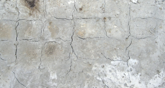
Ignoring proper curing protocols leads to severe structural and aesthetic problems on site. For example, premature moisture loss causes heavy surface dusting, plastic shrinkage cracking, and a significant loss of ultimate compressive strength. Furthermore, poorly cured concrete remains porous and vulnerable to water seepage and chemical attacks. Thus, skipping this step ruins your hard work and creates costly repair projects.
Common Practical Methods Used on Site
Builders use several effective techniques to keep fresh concrete moist and cool. First, water ponding creates shallow pools on flat slabs to keep surfaces continuously submerged. Second, continuous spraying and sprinkling work well for vertical walls and columns. Third, wet burlap coverings trap moisture against the concrete surfaces effectively. Finally, liquid membrane-forming curing compounds seal in moisture instantly after finishing.
Conclusion and Further Reading
In summary, concrete curing essentials involve maintaining ideal moisture and temperature levels to drive the hydration process forward. By avoiding premature drying and applying correct curing methods, you guarantee a strong and durable structure. If you want to explore more about advanced construction techniques and material testing, you can check out detailed guides on The Constructor.
References
Mindess, S., Young, J. F., & Darwin, D. (2003). Concrete. Prentice Hall.
Neville, A. M. (2011). Properties of Concrete. Pearson Education.
General procedure for design of solid slabs to BS Code.
1.Determine a suitable slab depth; you can easily estimate this by using the formula stated below;
Effective depth = span/( basic ratio × modification factor)
Span/effective depth ratios
For a simply supported design, the basic ratio is = 20 ( table 3.9, page 35 of BS 8110 part 1 : 1997). Use an initial modification factor (m.f) of 1.4.
Also the architect/ engineer may specify the slab thickness for you.
However, your slab design must satisfy deflection requirements otherwise you will have to redesign.
Ways to make your design slab satisfy deflection requirements if failed initially is to either increase slab thickness or amount of reinforcement or both.
2. Calculate the main and secondary reinforcement areas; you can do this by using the formulas stated in the BS code. ( Details later)
3. Check for excessive deflection ; as stated earlier in number 1, your design must satisfy deflection requirements.
4. Detailing requirements; the economical arrangement of steel reinforcement. You can refer to clause 3.12.10.3, BS 8110. An explanatory diagram is shown below for a simply supported case.
Detailing requirements for simply supported (a) & continuous ( b) slabs
It means that 40% of the reinforcement placed around the center of the slab ( which is critical) only, should extend to the edges of the slab ( which is less critical).
Explanation of other important points in solid slab design to BS 8110
Effective span of slab:
Referring to the diagram above, the effective span of slab refers to ‘A’ the distance between the centers of bearings, or the clear distance between supports ‘D’, plus effective depth of slab ‘d’.
Calculating steel areas.
In calculating the slab self weight, the overall depth of the slab referred to as ‘h’, should be used. h is the effective depth of slab plus allowance for cover to reinforcement plus half the assumed main steel diameter bar.
The self weight of the slab together with the dead and live load is used to determine the design moment ‘M’.
The value of M must be checked against the value of Mú which is the ultimate moment of resistance
Mú = 0.156fcubd²
Where b=1000mm and fcu = strength of concrete.
If Mú ≥ M then the slab doesn’t need compression reinforcement which is usually the case.
Main reinforcement steel areas
The area of reinforcement Aₛ can be determined using Aₛ= M÷(0.87𝑓yz) where,
M = design moment= WL²/8 (for simply supported slab)
W = design load of slab in kN/m²
L = span of slab in meters.
𝑓y= strength of steel
z = d[0.5 + √ (0.25 – K/0.9)] and
K= M / fcubd²
Secondary reinforcement steel areas
Secondary reinforcement also refers to distribution steel. As per BS 8110, it is calculated as follows;
Aₛ min = 0.24% Ac when 𝑓y = 250N/mm²
Aₛ min = 0.13% Ac when 𝑓y = 460N/mm²
Check that your slab design meets deflection requirements
Design service stress, fs = (2 𝑓y Asreq.) ÷ ( (3 Asprov), (table 3.10 page 36 of BS 8110 part 1 1997.)
Where Asreq & Asprov is the area of steel calculated and the area of steel provided, respectively.
Modification factor;
m.f = 0.55 + (477 – fs) ÷[120 ( 0.9 + M/bd²)] ≤ 2
Now this m.f is your actual m.f since it is a function of the area of steel calculated and area of steel provided.
Use this new m.f to replace the m.f you initially assumed to be 1.4 in the equation;
Effective depth; d = span/( basic ratio × modification factor).
you can also determine m.f from the table below
If the assumed value of d is greater than actual d, then deflection requirements are satisfied.
Crack widths
The BS code specifies that crack width should not exceed 0.3mm. except by calculation, the following rules should ensure crack width requirements are satisfied;
fy = 250N/mm² and depth of slab ≤ 250mm
or
fy = 460N/mm² and depth of slab ≤ 200mm
or
the percentage of reinforcement ( 100As/bd) ≤ 0.3%
Maximum bar spacing of reinforcement
BS code specifies that the clear distance between tension bars should be less than 3d or 750mm whichever is the lesser.
Example design of a simply supported solid slab
From the diagram of part of a floor plan shown above, I will be designing the panel labeled A.
The first thing to check is if the slab is a one or two way slab. By observing the dimensions relating to the slab panel, the longer side is
3401 + 587 + 1225 = 5213mm
The shorter side of the panel is
1150 + 1225 = 2375mm
Therefore longer side ÷ shorter side =
5213÷2375= 2.19 ≥ 2;
Panel A is a one way slab.
This means that the main reinforcement bars will span along the y- axis ( shorter side) and the distribution bar will span along the x – axis ( longer side).
direction of main reinforcement
Note that in a one way slab, the span of the slab is the shorter side. The span of the slab panel A being designed is 2375mm.
Further observation of the slab panel will show that its thickness (overall depth of slab) has been given as 150mm;
h = 150mm
Your duty as the designer is to calculate the required steel reinforcement and check if the design satisfies deflection requirements. If the slab thickness wasn’t given then you are free to assume a thickness and then check that it works.
Calculating the Design load.
The formula stated by BS code is
1.4Gk + 1.6Qk
where Gk = dead load
Qk = live load
dead load is the self weight of the slab plus finishes
Live load refers to variable or movable loads such as people, furniture etc, the slab carries. Live loads for different categories of buildings are stated in BS 6399 part 1: 1997.
Gk = weight of concrete x slab thickness
= 24kN/m³ x 0.15m ( slab thickness of 150mm)
= 3.6kN/m², plus finishes of say 1.2 kN/m² which gives a total gk of
4.8kN/m² ;
Gk = 4.8kN/m²
For private dwellings, Qk = 1.5kN/m² (see table 1 of BS 6399 part 1: 1997)
Design load = 1.4gk + 1.6qk
=( 1.4x 4.8 + 1.6 x 1.5) kN/m²
= 9.12kN/m² per m width ( slabs are designed per m width.)
Design moment M = WL²/8
where W = design load and L = span of slab
W=[ 9.12kN/m² x ( 2.375m)² ] / 8
= 6.43kNm
ultimate moment of resistance
Mu= 0.156fcubd²
Now d = effective depth of slab which can be estimated as overall depth of slab minus concrete cover to reinforcement minus half of main steel diameter
I.e. d = 150mm – 25mm – 6mm = 119mm.
( 25mm is concrete cover to reinforcement and 6mm is half the diameter of 12mm steel rod)
b = 1000mm ( slabs are designed per m width)
fcu = 25N/mm² ( strength of concrete)
Mu = 0.156 x 25N/mm² x 1000mm x (119mm)² = 55.2279 x 10⁶ Nmm
= 55.23kNm
Since M < Mu no compression reinforcement is required.
K= M / fcubd²
= 6.43 x 10⁶/ ( 25 x 1000 x 119²)
0.0182
z = d[0.5 + √ (0.25 – K/0.9)]
= 119[ 0.5 + ✓ ( 0.25 – 0.0182/0.9)]
= 116.54mm ≤ 0.95d
Limiting to 0.95d
0.95d = 113.05; use z= 113.05
Hence,
Aₛ= M÷(0.87fyz)
= 6.43 x 10⁶ ÷ ( 0.87 x 460 x 113.05)
Aₛ required. = 142.12 mm²/m width of slab
From fig. 1 shown above, use Y10 bars at 200mm spacings as main steel reinforcement
I.e.
Y10- 200
Aₛ provided = 393 mm²/m
Distribution reinforcement
Minimum Steel reinforcement specified by code = 0.13%bh
= 0.13% x 1000 x 150
Aₛ minimum required.= 195 mm²/m
With reference to fig 1, use Y10 – 250 bars. Aₛ = 314mm²/m
Note that the calculated required reinforcement is less than the minimum reinforcement specified by code, in this case the minimum reinforcement specified by code supersedes and should be used to select provided steel. Also using Y10- 200 as main and distribution steel is OK. It’s your design, you are in charge, just make sure you follow the code requirements and design laying emphasis on economy.
Checks
Deflectioncheck
Design service stress,
fs = 2 fy As req./ (3 As prov)
= 2×460×142.12÷(3×393)
=110.9N/mm²
fs = 110.9N/mm²
m.f = 0.55 + (477 – fs) ÷[120 ( 0.9 + M/bd²)] ≤ 2
= 0.55 + (477- 110.9)÷[120(0.9 + (6.43 x 10⁶/100 x119²)]
=2.80 ≤ 2
Since m.f is limited to 2,
Hence, m.f = 2
dmin = span / basic ratio x m.f
= 2375mm / (20 x 2)
= 59.375mm
59.375mm ≤ 119mm hence deflection is satisfied.
Crack width check
Since the slab is less than or equal to 200mm thick, crack width check is satisfied
Maximum spacing check
The reinforcement spacing of 200mm for main steel and 250 mm for distribution steel is less than 3d ( 3 x 119 = 357mm) hence maximum spacing check is satisfied.