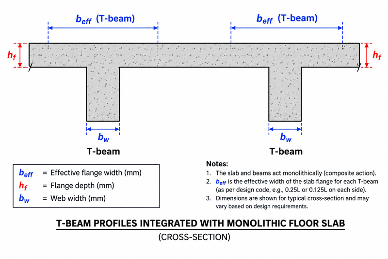
When you cast floor slabs and beams together in reinforced concrete construction, they do not work separately. Instead, the floor slab directly joins the top of the beam stem to resist compressive forces. This structural integration creates flanged beam actions, transforming standard rectangular beams into efficient T-beams or edge L-beams. Consequently, structural engineers save construction materials and improve load capacity by using the existing slab concrete as part of the beam.
What Are Flanged Beam Actions?
In monolithic floor systems, the slab provides a wide top section called the flange, while the beam stem forms the web underneath. Internal floor spans create T-shaped cross-sections, whereas boundary beams form L-shaped sections. Because concrete resists compression effectively, the slab flange carries high compressive stresses in sagging bending moment regions.
However, compressive stresses do not distribute uniformly across the full width of the floor slab. The stress level drops as you move further away from the beam web—a physical behavior known as shear lag. Therefore, standard codes establish an effective flange width ($b_{eff}$) to simplify design calculations. Engineers treat this effective portion as carrying a uniform stress level across its width.
Determining Effective Flange Width ($b_{eff}$)
To design flanged beams correctly, you must first calculate how much slab width actively assists the beam stem.
BS 8110 Approach
BS 8110 provides straightforward empirical rules based on the clear span distance between zero moment points ($L_0$):
- T-Beam Effective Width: $b_{eff} = b_w + 0.2 L_0$ (or actual slab width $b_{actual}$, whichever is smaller)
- L-Beam Effective Width: $b_{eff} = b_w + 0.1 L_0$ (or actual overhang width $b_w + b_1$, whichever is smaller)
Here, $b_w$ represents the web width. For a simply supported beam, $L_0$ equals the total span length $L$. For continuous spans, designers estimate $L_0$ as $0.7 L$.
Eurocode 2 (EC2) Approach
Eurocode 2 uses a more detailed calculation. EC2 evaluates each side overhang independently before adding the web width:
- $b_{eff} = \sum b_{eff,i} + b_w \le b_{actual}$
- $b_{eff,i} = 0.2 b_i + 0.1 L_0 \le 0.2 L_0$ (and $b_{eff,i} \le b_i$)
In this formula, $b_i$ represents half the clear distance to the adjacent beam web. Consequently, Eurocode 2 yields a larger, more realistic effective width for wider beam spacings than BS 8110.
Key Design Scenarios in Flanged Beam Actions
Once you calculate $b_{eff}$, you must locate the neutral axis depth ($x$) relative to the slab flange thickness ($h_f$). This step reveals how flanged beam actions carry the compressive load.
Scenario A: Neutral Axis Inside the Flange ($x \le h_f$)
In most practical floor designs, the flange provides a massive compression area. As a result, the ultimate compressive stress block stays entirely inside the slab depth ($h_f$). You simply analyze the member as a wide rectangular beam with width $b_{eff}$ and effective depth $d$.
Scenario B: Neutral Axis Extends Into the Web ($x > h_f$)
When a beam experiences heavy bending moments or features a thin slab, the stress block penetrates down into the beam web stem. Consequently, you must divide the total concrete compressive force ($F_c$) into two separate parts:
- $F_{cf}$: Compression carried by the flange overhangs ($b_{eff} – b_w$).
- $F_{cw}$: Compression carried by the central web stem ($b_w$).
Step-by-Step Procedure to Calculate Neutral Axis Depth ($x$)
You can find the neutral axis depth $x$ using a logical step-by-step process:
- Calculate the ultimate design bending moment $M$ from your structural analysis.
- Determine the maximum moment capacity of the slab flange alone ($M_f$) using the equation: $M_f = F_c \times (d – 0.5 h_f)$.
- Compare $M$ against $M_f$.
- If $M \le M_f$, the stress block remains within the flange thickness ($x \le h_f$). You can easily compute the lever arm $z$ using rectangular beam equations.
- If $M > M_f$, the stress block enters the web stem ($x > h_f$). You must sum the moments of $F_{cf}$ and $F_{cw}$ about the tension reinforcement to solve for $x$ directly.
Comparing BS 8110 Code and Eurocode 2
Although both standard codes share the same physical principles, key differences exist in their analytical execution:
- Effective Width Precision: BS 8110 applies simplified single-factor formulas ($0.2 L_0$ and $0.1 L_0$). In contrast, Eurocode 2 considers clear overhang spans ($b_i$) directly, offering higher structural efficiency.
- Concrete Stress Block: BS 8110 uses a rectangular stress block factor of $0.45 f_{cu}$ over a depth of $0.9 x$. On the other hand, Eurocode 2 uses $0.567 f_{ck}$ over a depth of $0.8 x$ (for concrete grades up to $C50/60$).
- Material Strengths: BS 8110 bases calculations on characteristic cube strength ($f_{cu}$), whereas Eurocode 2 uses cylinder strength ($f_{ck}$).
Simple Worked Examples for BS 8110 and Eurocode 2
Let us compare calculations for a simply supported T-beam with these parameters:
- Clear Span $L = L_0 = 6.0\text{ m}$ ($6000\text{ mm}$)
- Web Width $b_w = 300\text{ mm}$
- Flange Depth $h_f = 150\text{ mm}$
- Effective Depth $d = 500\text{ mm}$
- Beam Center-to-Center Spacing = $3.0\text{ m}$ ($b_{actual} = 3000\text{ mm}$)
- Design Moment $M = 350\text{ kNm}$
BS 8110 Calculation Example
First, calculate effective flange width:
$b_{eff} = b_w + 0.2 L_0 = 300 + (0.2 \times 6000) = 1500\text{ mm}$ (less than $b_{actual} = 3000\text{ mm}$).
Assume concrete grade $f_{cu} = 30\text{ N/mm}^2$ and steel strength $f_y = 460\text{ N/mm}^2$.
Calculate maximum flange moment capacity:
$M_f = 0.45 f_{cu} b_{eff} h_f (d – 0.5 h_f) \times 10^{-6}$
$M_f = 0.45 \times 30 \times 1500 \times 150 \times (500 – 75) \times 10^{-6} = 1290.9\text{ kNm}$
Since $M = 350\text{ kNm} < 1290.9\text{ kNm}$, the neutral axis sits inside the flange ($x \le h_f$).
Next, calculate factor $K$:
$K = M / (f_{cu} b_{eff} d^2) = (350 \times 10^6) / (30 \times 1500 \times 500^2) = 0.0311$
Calculate lever arm $z$:
$z = d \times [0.5 + \sqrt{0.25 – (K / 0.9)}] = d \times [0.5 + \sqrt{0.25 – (0.0311 / 0.9)}] = 0.963 d$
Limit lever arm to $0.95 d$: $z = 0.95 \times 500 = 475\text{ mm}$.
Calculate required tension steel area $A_s$:
$A_s = M / (0.95 f_y z) = (350 \times 10^6) / (0.95 \times 460 \times 475) = 1686\text{ mm}^2$.
Eurocode 2 Calculation Example
First, evaluate overhang distance $b_1 = (3000 – 300) / 2 = 1350\text{ mm}$.
$b_{eff,1} = (0.2 \times 1350) + (0.1 \times 6000) = 270 + 600 = 870\text{ mm}$.
Since $870\text{ mm} \le 0.2 L_0 = 1200\text{ mm}$, use $b_{eff,1} = 870\text{ mm}$.
$b_{eff} = b_w + 2 b_{eff,1} = 300 + (2 \times 870) = 2040\text{ mm}$.
Assume concrete grade $C25/30$ ($f_{ck} = 25\text{ N/mm}^2$) and steel strength $f_{yk} = 500\text{ N/mm}^2$.
Design concrete strength $f_{cd} = f_{ck} / 1.5 = 16.67\text{ N/mm}^2$.
Calculate maximum flange moment capacity:
$M_f = f_{cd} b_{eff} h_f (d – 0.5 h_f) \times 10^{-6}$
$M_f = 16.67 \times 2040 \times 150 \times (500 – 75) \times 10^{-6} = 2167.9\text{ kNm}$
Because $M = 350\text{ kNm} < 2167.9\text{ kNm}$, $x \le h_f$.
Calculate factor $K$:
$K = M / (f_{ck} b_{eff} d^2) = (350 \times 10^6) / (25 \times 2040 \times 500^2) = 0.0275$
Calculate lever arm $z$:
$z = d \times 0.5 \times [1 + \sqrt{1 – 3.53 K}] = d \times 0.5 \times [1 + \sqrt{1 – 3.53 \times 0.0275}] = 0.975 d$
Limit lever arm to $0.95 d$: $z = 0.95 \times 500 = 475\text{ mm}$.
Calculate design yield strength $f_{yd} = 500 / 1.15 = 434.78\text{ N/mm}^2$.
$A_s = M / (f_{yd} z) = (350 \times 10^6) / (434.78 \times 475) = 1695\text{ mm}^2$.
Further Reading
Understanding flanged beam actions allows structural engineers to design lighter and more economical concrete structures. While BS 8110 offers fast calculations using empirical rules, Eurocode 2 delivers superior structural optimization through detailed effective width equations. To deepen your understanding of concrete design standards and structural mechanics, you can explore detailed design guidance on The Concrete Centre website.
References
- British Standards Institution. (1997). BS 8110-1: Structural use of concrete – Code of practice for design and construction. BSI.
- European Committee for Standardization. (2004). Eurocode 2: Design of concrete structures – Part 1-1: General rules and rules for buildings (EN 1992-1-1). CEN.
- Mosley, W. H., Bungey, J. H., & Hulse, R. (2012). Reinforced Concrete Design to Eurocode 2 (7th ed.). Palgrave Macmillan.