What is the Ki Cordless Kitchen Standard? 2.2kW Inductive Power Specs Explained

modern smart kitchen showcasing cordless appliances

Imagine a kitchen with completely bare countertops and no messy power cords. Smart home early adopters are closely watching a new technology that makes this design dream a reality. This innovation relies heavily on the Ki Cordless Kitchen standard, which completely changes how we power our everyday appliances. By removing traditional plugs, this technology creates a cleaner, safer, and much more flexible cooking space.

Wireless Power at Scale with the Ki Cordless Kitchen Standard

The Wireless Power Consortium (WPC) created this groundbreaking technology. You might already know the WPC because they developed the famous Qi charging standard for smartphones. However, while smartphones only need a few watts of electricity to charge, kitchen appliances require massive amounts of energy. Consequently, this new kitchen system safely delivers up to 2.2 kilowatts (2,200 watts) of inductive power straight through standard stone or wood countertops.

For example, you can place a high-powered blender or a water kettle directly on your kitchen island. The hidden transmitter beneath the counter transfers electricity invisibly into the appliance. Therefore, you do not need any visible outlets or wires to boil water or mix a smoothie. This massive electrical specification leap ensures that even your most demanding kitchen tools run at full capacity without a physical connection.

NFC Safety Specs of the Ki Cordless Kitchen Standard

Safety remains a top priority when dealing with 2,200 watts of wireless electricity. To prevent accidents, the Ki Cordless Kitchen standard uses strict Near Field Communication (NFC) constraints. Specifically, cordless appliances contain integrated NFC transceivers, such as the advanced ST25R3918 chip. These chips establish a constant, secure communication loop with the transmitter hidden under the counter.

Before the base station sends any high wattage, it must verify the appliance. The chip and the transmitter constantly negotiate power delivery requirements in real-time. Furthermore, this intelligent communication provides an immediate safety shut-off. If a non-certified object, like a metal fork or a human hand, disrupts the electromagnetic field, the base station instantly turns off the power to avoid any danger or burns.

Standby Energy Harvesting Features

Another impressive part of this specification involves how appliances handle power when they are idle under the Ki Cordless Kitchen standard. The technology includes a clever standby energy harvesting feature. This specification allows an appliance to harvest micro-energy from the transmitter even when you are not actively cooking. In addition, this low-power transfer happens continuously without activating the full 2.2kW power grid.

Because of this micro-energy, the digital user interfaces and LCD screens on your appliances stay awake at all times. For instance, your blender’s digital menu will light up the moment you place it on the counter. You can adjust settings or read timers immediately. The appliance achieves this convenience without drawing the massive wattage required for heavy heating or high-speed blending.

Embracing the Future of Smart Kitchens

Kitchen renovators and tech enthusiasts will surely benefit from this cordless revolution. The Ki Cordless Kitchen standard perfectly blends high-power capability with intelligent safety systems to redefine modern home design. As more manufacturers adopt these specifications, traditional power cords will soon become a thing of the past. To explore more about how wireless power is transforming modern homes, check out the official Wireless Power Consortium website for deep dives into upcoming smart appliance specifications.

References

  • Wireless Power Consortium (WPC). “The Ki Cordless Kitchen Standard.” wirelesspowerconsortium.com.
  • STMicroelectronics. “ST25R3918 High Performance NFC Universal Device and Car Access Reader Datasheet.” st.com.

Shape Memory Alloy vs Voice Coil Motor OIS: Smartphone Camera Guide

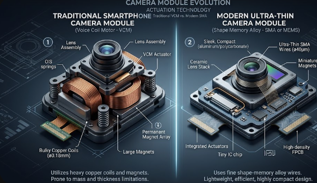
 Graphic comparing Shape Memory Alloy vs Voice Coil Motor OIS hardware inside a smartphone.

Have you ever wondered how your smartphone takes sharp photos even when your hands shake? The secret lies in Optical Image Stabilization (OIS). Recently, a big tech battle has emerged regarding Shape Memory Alloy vs Voice Coil Motor OIS systems in flagship phones. Manufacturers want to give you the best camera experience, but they use different mechanical methods to achieve it. Understanding this technology helps you make better buying decisions when comparing top-tier phone cameras.

The Mechanical Shift in Smartphone Cameras

For years, phone companies relied heavily on Voice Coil Motors (VCM) to stabilize lenses. A standard VCM setup uses heavy permanent magnets and copper wire coils. When electrical current passes through these coils, it creates a magnetic field that physically shifts the entire lens assembly to counteract your hand movements. While this method works well, it requires significant physical space and adds noticeable weight to the camera module.

In contrast, Shape Memory Alloy (SMA) actuators offer a completely different mechanical approach. Instead of bulky magnets, SMA technology uses specialized, hair-thin metal wires. These unique wires physically contract and expand when engineers apply a precise electrical current to them. This thermal reaction moves the lens rapidly and accurately, completely changing how engineers design modern mobile camera systems.

Weight and Size Benefits of Shape Memory Alloy vs Voice Coil Motor OIS

As smartphone sensors grow larger, space inside the phone body becomes extremely valuable. Because SMA completely eliminates bulky magnets and copper coils, it drastically reduces the physical footprint of the camera module. Therefore, manufacturers can pack massive image sensors into thin phones without creating huge, heavy camera bumps.

Furthermore, removing magnets solves a major engineering headache. Traditional VCM magnets can cause severe magnetic interference with neighboring lenses in a multi-camera array. For example, the magnet from a telephoto lens might disrupt the main camera. Because SMA actuators do not use magnets, they eliminate this risk entirely. Consequently, phone brands can place multiple high-powered cameras close together without performance issues.

Performance Battle: Multi-Axis Stabilization Limits

When we look at speed and accuracy, the difference between these two technologies becomes even clearer. A standard 4-wire SMA configuration allows for superior X and Y-axis stabilization. In addition, it enables active lens tilt, which corrects for rotational movements when you walk or run.

As a result, SMA systems react to micro-tremors from your hand with mathematically faster response times than spring-based VCM setups. Traditional VCM systems rely on tiny mechanical springs to hold the lens, which can wobble or lag during sudden movements. SMA wires pull tightly and release instantly, giving you incredibly smooth video and sharper low-light photos.

Final Thoughts on Shape Memory Alloy vs Voice Coil Motor OIS

Choosing a flagship phone often comes down to camera performance. While VCM remains a reliable and affordable choice for mid-range devices, SMA represents the future for premium photography. It gives you bigger sensors, lighter phone designs, and faster stabilization. To learn more about advanced mobile hardware and camera mechanics, check out Android Authority for deep dives into upcoming smartphone sensor tech.

References

  • Cambridge Mechatronics. (2024). Shape Memory Alloy (SMA) Technology for Smartphone Cameras.
  • IEEE Transactions on Magnetics. (2023). Comparison of Voice Coil Actuators and Smart Materials in Miniature Optical Systems.
  • Image Sensors World. (2025). Trends in Mobile Camera Modules: OIS and Actuator Evolutions.

Why PCIe 6.0 Retimers in AI Data Fabrics Are Critical for Speed

A detailed hardware diagram showing PCIe 6.0 retimers in AI data fabrics restoring signal strength between processors.

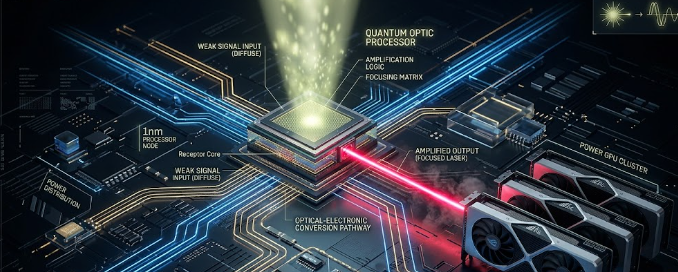
Artificial intelligence (AI) models require massive amounts of data to train and run efficiently. Because of this demand, modern data centers must move information between processors and memory at lightning speeds. This is why engineers now use PCIe 6.0 retimers in AI data fabrics to maintain clear communication lines. Without these specialized chips, high-speed servers would simply fail to process complex AI workloads.

The Physics Problem: Signal Integrity Bottlenecks

The latest PCIe 6.0 standard is incredibly fast, reaching transfer speeds of 64 Gigatransfers per second (GT/s). However, running data at this extreme frequency creates a massive physics problem known as signal degradation. When data travels at these speeds over standard motherboard copper traces, the electrical signal weakens almost immediately.

Consequently, the data distorts before it even reaches its destination. Think of this problem like shouting down a very long, windy tunnel. By the time your voice reaches the other side, the wind has turned your words into muffled, useless noise.

How Retimers Fix the Signal Loss

To solve this physical limitation, hardware architects install chips called retimers along the data path. These chips act like intelligent radio repeaters. First, the retimer catches the fading, noisy data signal before it degrades completely. Next, it cleans up the electrical noise and rebuilds the data packet. Finally, it retransmits a perfect, brand-new signal to the next component.

Therefore, using PCIe 6.0 retimers in AI data fabrics ensures that data travels across longer distances inside the server without any corruption. They are absolutely essential for keeping the internal data highway flowing smoothly.

Why Low Latency Matters for PCIe 6.0 Retimers in AI Data Fabrics

Speed is not just about bandwidth; it is also about latency. When you pool expensive GPU resources together for AI workloads, even a microscopic delay can ruin performance. Because of this issue, new hardware like Microchip’s XpressConnect retimers achieves an ultra-low latency of under 12 nanoseconds.

In the world of AI training, every single nanosecond counts. If one GPU stalls while waiting for data from another chip, the entire system slows down. This delay creates a bottleneck that wastes expensive computing power and increases operational costs.

By keeping latency below 12 nanoseconds, PCIe 6.0 retimers in AI data fabrics eliminate these microscopic data stalls. As a result, massive clusters of GPUs can work together seamlessly as if they were a single, giant processor.

Memory Disaggregation Specs: CXL 3.1 to the Rescue

Another major breakthrough in modern data centers is the Compute Express Link (CXL) 3.1 protocol. Traditionally, each processor socket has a strict physical limit on how much RAM it can hold. CXL 3.1 changes this rule entirely by introducing a concept called memory disaggregation.

This specific protocol allows multiple servers or GPUs to share a single, massive pool of external RAM. Instead of being trapped inside one server socket, the memory sits in an external pool that any processor can access on demand.

However, to connect these massive memory pools to your GPUs, you need an incredibly reliable connection. This is exactly where PCIe 6.0 retimers in AI data fabrics become valuable. They ensure the CXL 3.1 signals remain crisp and fast over the longer cables required for shared memory hardware.

Conclusion

Building efficient AI systems requires both massive bandwidth and perfect signal control. By combining CXL 3.1 memory pools with high-speed PCIe connections, data centers can handle the toughest AI workloads. Ultimately, deploying PCIe 6.0 retimers in AI data fabrics solves the core physics and latency issues of modern computing. For further technical details on how these components integrate into data centers, you can read more on the PCI-SIG Official Website.

References

  • Compute Express Link Consortium. (2023). CXL 3.1 Specification Features and Advancements.
  • Microchip Technology Inc. (2024). XpressConnect Retimers for PCIe 6.0 and CXL 3.0 Ultra-Low Latency Solutions.
  • PCI-SIG. (2022). PCI Express Base Specification Revision 6.0.

VESA ClearMR 14000: The Ultimate Guide to Display Motion Blur

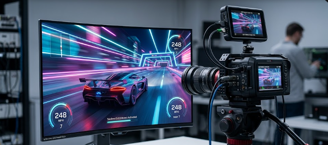
 A high-speed digital camera measuring VESA ClearMR 14000 performance on a gaming monitor.

Are you tired of buying a gaming monitor that promises lightning speeds but still delivers a blurry mess during fast action? You are certainly not alone. Therefore, you need to understand the VESA ClearMR 14000 standard. This brand-new metric is changing how we buy screens today. Previously, companies sold monitors using confusing terms that did not match real-world viewing. However, the VESA ClearMR 14000 certification guarantees that the screen handles motion perfectly. Whether you play competitive games or watch fast-moving sports, this standard helps you pick the right display. In this article, we will explore why this new rating matters. Furthermore, we will show you how it easily beats older measurement methods.

Why Outdated Metrics Fail Gamers

For many years, manufacturers used the Gray-to-Gray (GtG) metric to sell monitors. You probably saw boxes proudly showing “1ms GtG.” Unfortunately, this old specification frequently misleads buyers. GtG only measures how fast a single pixel changes from one shade of gray to another. Consequently, it completely ignores how your eyes actually see a moving picture full of bright colors.

Manufacturers often use software tricks to speed up these gray-to-gray transitions. As a result, you might buy a “1ms” monitor and still experience terrible motion blur during a fast gaming match. To fix this obvious problem, the display industry needed a better testing method. That is exactly where the new testing standard steps in to save the day.

How VESA ClearMR 14000 Measures Real Blur

Unlike old methods, the VESA ClearMR 14000 standard uses advanced physical tools to test screens. Testers point high-speed digital cameras and precise colorimeters directly at the monitor. Next, they record exactly how the pixels handle fast-moving objects on the screen. This rigorous process measures true motion blur in a way that perfectly matches human eyesight. Consequently, you get a realistic score based on the Clear Motion Ratio (CMR).

So, what does this specific tier mean for your eyes? When a monitor earns a VESA ClearMR 14000 badge, it delivers an incredibly sharp picture. Specifically, this tier dictates that sharp pixels outnumber blurry pixels by a massive factor of 135 to 145 times. For example, if you watch a fast-moving soccer ball, you will see exactly one slightly blurry pixel for every 135 perfectly clear ones.

Panel Technologies Reaching VESA ClearMR 14000

Achieving this elite certification requires serious hardware power. Today, the latest 2026 Tandem OLED monitors easily match up against these demanding tiers. Because OLED pixels create their own light, they turn on and off almost instantly. Furthermore, modern high-zone Mini-LED monitors also perform exceptionally well in these tests. These advanced Mini-LED panels use thousands of tiny lights to control brightness with incredible speed.

Both of these modern panel architectures feature rapid pixel response profiles. Consequently, they easily earn higher ClearMR certifications from testers. When you compare an older LED screen to a new 2026 Tandem OLED, the visual difference feels massive. The newer technology eliminates the annoying ghosting effect completely. Therefore, your competitive games look smoother, sharper, and much more realistic.

Wrapping Up Your VESA ClearMR 14000 Upgrade

Upgrading your monitor is a big investment, so you should always look for accurate performance numbers. In conclusion, you should ignore the outdated gray-to-gray times and look for the VESA ClearMR 14000 logo instead. This modern standard gives you total peace of mind and guarantees a crystal-clear image. As you search for your next competitive gaming screen, keep this powerful metric in mind to ensure you get the best value. Finally, if you want to dive deeper into how professionals test screen clarity and motion reduction, you can read more at Blur Busters.

References

  • Video Electronics Standards Association (VESA). (2026). ClearMR Display Standard Specifications.
  • Blur Busters. (2026). Understanding Motion Blur Reduction and Display Metrics.

 CXL 3.1 Fabric Topologies: Memory Pooling Specs in Modern Workstations

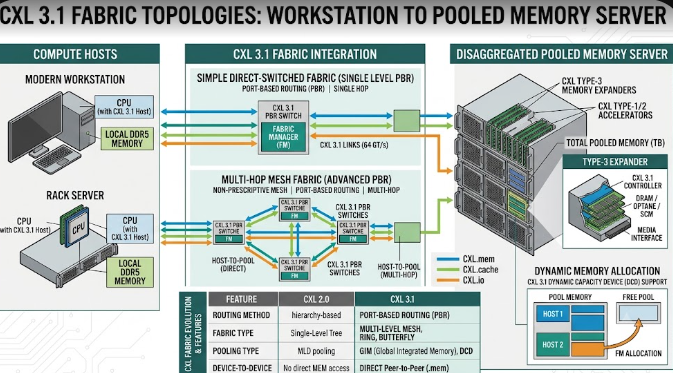
 Illustration showing CXL 3.1 Fabric Topologies connecting a modern workstation to a pooled memory server.

Enterprise IT professionals and structural engineers constantly need more computing power. To meet this demand, technology companies have introduced CXL 3.1 Fabric Topologies. Consequently, modern workstations can now handle massive data loads better than ever before. CXL stands for Compute Express Link. In essence, it is a high-speed connection that changes how computer parts talk to each other. Furthermore, this new specification allows computers to share memory over a network. Therefore, data analysts and engineers can run heavy simulations without slowing down their machines. In this article, we will explore how this technology works and why it matters for your heavy-duty computing tasks.

Direct Core-to-Memory Links in CXL 3.1 Fabric Topologies

First, let us look at direct core-to-memory links. The Compute Express Link (CXL) 3.1 specification runs over the fast PCIe Gen 6 infrastructure. Basically, it creates a superhighway between the computer’s processor (CPU) and the memory (RAM).

Traditionally, a CPU could only use the RAM plugged directly into its own motherboard. However, CXL 3.1 Fabric Topologies change this old setup entirely. Now, a CPU can access external RAM pools over a fast network. Specifically, it does this with near-zero latency overhead. Latency simply means delay. Because the delay is so tiny, the CPU treats this external memory exactly like its own internal memory. For example, if a civil engineer loads a massive bridge design, the computer pulls memory from the external pool instantly.

Dynamic Resource Allocation for Heavy Tasks

Next, we must discuss dynamic resource allocation. This feature is a game-changer for extreme workstation planners. Modern workflows require a flexible architectural specification. With CXL 3.1 Fabric Topologies, a master workstation can dynamically borrow blocks of memory from a centralized server fabric.

Imagine you are running massive structural simulations or complex 3D rendering tasks for a skyscraper. Suddenly, your workstation runs out of memory. Previously, the computer would crash or slow down drastically. Instead, the system automatically borrows extra memory from the centralized pool just for that specific task. Once the simulation finishes, the workstation returns the memory to the server. Consequently, other computers on the network can use that same memory block later. This process saves money and boosts overall efficiency.

The Cache Coherency Metric in CXL 3.1 Fabric Topologies

Finally, we must understand the cache coherency metric. Cache coherency remains the foundational specification of CXL technology. Without it, sharing memory would cause massive data corruption across the server.

When multiple computer parts share the same memory, they need to know what the others are doing. For instance, suppose a graphics card (GPU) modifies data in the pooled memory during a 3D rendering job. Thanks to CXL 3.1 Fabric Topologies, the main CPU instantly recognizes this change. Therefore, the CPU will not accidentally use the old, outdated data. The system constantly checks and updates all data across the network. As a result, engineers enjoy smooth, error-free simulations every single time.

In conclusion, this technology prepares your IT infrastructure for the future of civil engineering. If you want to learn more about the technical side of the Compute Express Link standard, please visit the official CXL Consortium website for further reading.

References

  • Compute Express Link Consortium. (2024). CXL 3.1 Specification.
  • PCI-SIG. (2024). PCI Express (PCIe) 6.0 Specification.

 High-Gain Wi-Fi 7/8 Antennas: Fixing Dead Zones in Complex Homes

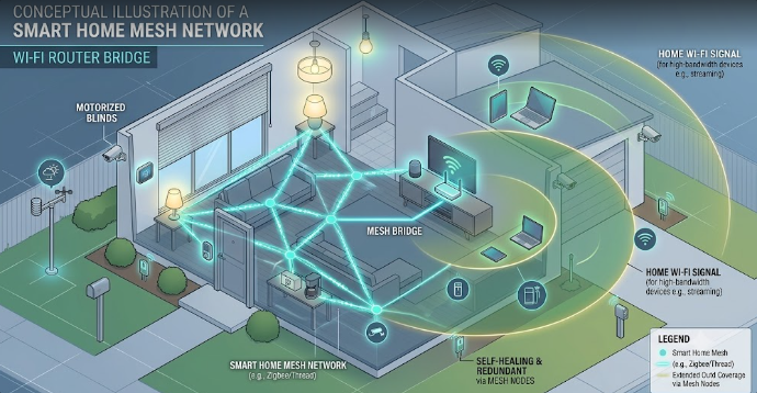
A smart home network router utilizing High-Gain Wi-Fi 7/8 Antennas to broadcast strong signals down a hallway.

Do you struggle with wireless dead zones in your large or multi-unit home? If you are a DIY home builder or a smart home network installer, you know how frustrating weak signals can be. Fortunately, High-Gain Wi-Fi 7/8 Antennas offer a powerful solution to this exact problem. However, to get the best results, you must understand how antenna specifications work. Many users believe that a bigger antenna simply creates a more powerful signal. In reality, the secret lies in how the antenna shapes and directs the energy throughout your living space.

Decoding the dBi Rating in High-Gain Wi-Fi 7/8 Antennas

When you look at a router specification sheet, you will see a number followed by “dBi.” This term stands for decibels isotropic. Specifically, it measures how effectively an antenna focuses its wireless signal in a particular direction.

It is crucial to understand that a higher dBi rating does not mean the router produces more overall power. Instead, the antenna simply reshapes the existing signal. Think of a standard lightbulb versus a flashlight. A standard bulb sends light in all directions, but it cannot reach very far. On the other hand, a flashlight focuses that exact same amount of light into a tight, powerful beam. Therefore, High-Gain Wi-Fi 7/8 Antennas act just like flashlights for your home network data.

Signal Geometry: Shapes for Different Home Layouts

Antenna gain directly changes the physical shape of your wireless coverage. For instance, a low-gain antenna, such as a 2 dBi model, creates a round, donut-shaped bubble. This bubble spreads the signal evenly in all directions, including up and down. Consequently, this shape works perfectly for multi-story properties where devices sit on different floors.

Conversely, high-gain directional antennas (ranging from 5 dBi to 9 dBi) squash that bubble into a flat, elongated disc. This design works wonderfully for punching signals down long hallways or across wide, open outdoor spaces. However, because the disc is flat, it sends very little signal upward or downward. If you place a high-gain router in a multi-story home, the upper floors might suffer from terrible reception.

Beamforming Synergy with Next-Gen Wi-Fi

Modern wireless technology makes these specialized antennas even smarter. Specifically, Wi-Fi 7 and Wi-Fi 8 utilize an advanced feature called explicit beamforming. This technology allows the router to locate your specific devices and aim concentrated data beams directly at them.

When you combine beamforming with High-Gain Wi-Fi 7/8 Antennas, you achieve outstanding network performance. The high-gain antenna provides a tightly focused signal disc, while beamforming dynamically steers the data beams within that disc to hit high-bandwidth targets. Therefore, your smart TVs and gaming consoles receive a laser-focused connection, which effectively eliminates lag.

Choosing the Right Setup for Your Home

Ultimately, you must match your antenna choice to your building layout. If you manage a sprawling, single-story home or a large outdoor property, then High-Gain Wi-Fi 7/8 Antennas are an excellent choice. They will push the signal horizontally to reach every far corner. For multi-story homes, you should stick with lower-gain options to ensure good vertical coverage. For deeper technical insights into wireless networking standards and next-generation hardware, you can read the latest updates on the official Wi-Fi Alliance website.

References

  • IEEE Xplore Digital Library. (2025). Analysis of Antenna Gain and Beamforming in Next-Generation Wireless Networks.
  • Wi-Fi Alliance. (2026). Wi-Fi 7 and Wi-Fi 8 Technical Specifications and Deployment Guide.