Understanding Monitor Overdrive and Response Time G2G Specs

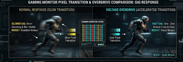
 A technical diagram illustrating how monitor overdrive improves response time G2G specs to reduce ghosting during competitive gaming.

When you buy a gaming monitor, the retail box usually boasts an ultra-fast speed like 1ms or 0.5ms. However, competitive gamers know that these basic marketing numbers do not tell the whole story. To truly understand motion clarity, you must look closely at the response time G2G specs. This specific metric determines how fast your monitor can update moving images during fast-paced gameplay. Consequently, understanding this specification will help you calibrate your screen for the ultimate competitive edge.

Understanding the Physics Behind Response Time G2G Specs

Grey-to-Grey (G2G) measures the exact time in milliseconds (ms) that a display pixel takes to transition from one shade of grey to another shade. Monitor manufacturers use grey shades for testing because liquid crystals change between greys much faster than they change between fully saturated colors. Therefore, checking the response time G2G specs gives a realistic average of daily monitor performance during dynamic gameplay.

In contrast, moving picture response time (MPRT) measures how long a pixel remains continuously visible on the screen. While MPRT relates directly to the motion blur your eyes track, G2G focuses entirely on the physical speed of the pixel itself. Consequently, a monitor might have a great MPRT score due to backlight strobing but still suffer from slow underlying pixel transitions.

How the Overdrive Voltage Protocol Accelerates Your Screen

To speed up pixel transitions, monitor firmware uses a clever trick called “Overdrive.” Under normal conditions, liquid crystals twist at a native physical limit when they receive standard voltage. However, the overdrive protocol temporarily pumps a much higher electrical voltage into the liquid crystals or pixel controllers.

[Standard Voltage]  —> Slow Crystal Twist —> High Response Time
[Overdrive Voltage] —> Fast Crystal Twist —> Low Response Time (Faster)

This sudden surge of power forces the crystals to twist and change states much faster than their native limits. As a result, the monitor achieves those coveted 1ms response times advertised on the box. For example, if a pixel needs to shift from dark grey to light grey, overdrive gives it an aggressive electrical push. Therefore, active overdrive significantly reduces traditional motion blur during intense gaming sessions.

The Dark Side: Inverse Ghosting and Pixel Overshoot

Although overdrive improves speed, aggressive settings introduce a critical trade-off known as pixel overshoot. When you crank the overdrive setting too high, the excessive voltage forces the pixel to zoom past its targeted color value. For instance, a pixel aiming for a medium grey might accidentally shoot all the way to bright white before settling back down.

This physical error creates a distracting visual artifact called inverse ghosting. Instead of a smooth trailing smear, you will see a prominent, dark shadow trail or a bright halo behind moving objects. Therefore, maximizing your response time G2G specs through extreme overdrive often ruins overall image quality. Competitive gamers must find a balanced setting that provides speed without causing these ugly artifacts.

Why You Need Variable Overdrive in VRR Ecosystems

The challenge gets more complicated when you use Variable Refresh Rate (VRR) technologies like G-Sync or FreeSync. These tools synchronize your monitor‘s refresh rate directly with your game’s changing framerate. Consequently, if your game drops from 144 frames per second to 60 frames per second, your monitor slows down its refresh rate to match.

Because the refresh rate changes instantly, a static overdrive voltage becomes a major problem. A high voltage that works perfectly at 144Hz will severely overshoot at 60Hz because the pixels have more time between refreshes. Therefore, high-end gaming monitors must feature dynamic or variable overdrive. This feature ensures the overdrive voltage continuously scales its power output in lockstep with real-time framerate fluctuations. As a result, you get clean transitions without overshoot, even when your game performance drops during heavy combat.

Finding the Perfect Balance for Competitive Play

Ultimately, tuning your monitor requires a careful balance between raw speed and visual clarity. You should test different overdrive profiles in your monitor’s on-screen display (OSD) menu to see which one works best. Usually, the middle or “Normal” setting yields the best response time G2G specs without triggering horrible inverse ghosting. To dive deeper into testing your display and optimizing motion performance, you can read more technical breakdowns on TFT Central.

References

  • Blur Busters. (2021). LCD Motion Artifacts: Ghosting vs. Inverse Ghosting.
  • TFT Central. (2023). Response Time Testing and Overdrive Explanations.

 IEEE 802.11bb Li-Fi: Wireless Tech Beyond Radio Frequencies

 An enterprise office featuring an IEEE 802.11bb Li-Fi system transmitting secure data through near-infrared light.

The demand for faster and more secure wireless connections grows every single day. Traditional Wi-Fi networks often face heavy congestion because too many devices share the same radio waves. To solve this problem, a revolutionary technology has emerged to change how we transmit data. The IEEE 802.11bb Li-Fi standard introduces a global framework that uses light instead of radio frequencies to connect devices to the internet. This exciting development offers a powerful alternative for IT professionals and enterprise network architects who need hyper-secure, high-speed networks.

Shifting to Light with the IEEE 802.11bb Li-Fi Standard

Traditional Wi-Fi transmits data using radio frequencies, usually in the 2.4 GHz or 5 GHz bands. However, users heavily crowd these airwaves today. Think of a busy highway during rush hour; too many cars slow everyone down. In contrast, the IEEE 802.11bb Li-Fi standard shifts data transmission into the optical spectrum. Specifically, this new technology utilizes near-infrared light in the 800 nm to 1000 nm waveband to carry information.

By using light waves, this system completely avoids radio frequency gridlock. Infrared light transmits data seamlessly without interfering with your existing wireless systems. For instance, hospital rooms or military bases can use light waves safely without disrupting sensitive electronic equipment. Therefore, this technology opens up a massive, unused spectrum that provides a clean and clear channel for high-speed data.

Breaking Down Throughput in the IEEE 802.11bb Li-Fi Specs

Network architects always demand reliable and scalable speeds for modern enterprise setups. Fortunately, the IEEE 802.11bb Li-Fi standard delivers impressive throughput specifications that meet these professional needs. The technology provides a scalable performance model depending on your specific environment and hardware layout. For basic operations, it offers a highly stable baseline speed starting at a 10 Mbps floor.

On the upper end of the spectrum, the standard can reach a blistering ceiling of 9.6 Gbps. This maximum speed matches the top capabilities of Wi-Fi 6. Consequently, users can download massive files, stream high-definition media, or transfer large data packages in seconds. The wide speed range ensures that the network remains highly stable even when environmental conditions fluctuate.

Physical Security by Design in IEEE 802.11bb Li-Fi Networks

Data security remains a top priority for corporate and enterprise networks. Radio waves easily pass through drywall, glass, and wood, which exposes networks to hackers outside the building. The IEEE 802.11bb Li-Fi technology solves this critical issue through physical design. Because light cannot penetrate solid walls, the data stays strictly confined within a single room.

This strict line-of-sight requirement fundamentally changes how we protect sensitive data. Mathematically, it drops the probability of external network eavesdropping or malicious jamming to near zero. A bad actor cannot intercept your signal from the parking lot because the light waves do not reach them. As a result, this system provides unmatched physical security for banks, government offices, and research facilities.

The Perfect Synergy: How IEEE 802.11bb Li-Fi Combines with Wi-Fi

You might wonder if you need to replace your entire Wi-Fi infrastructure to adopt this new tech. Fortunately, you do not have to throw away your old routers. Standard devices will soon utilize hybrid network architectures to blend both worlds perfectly. These hybrid systems deploy the IEEE 802.11bb Li-Fi standard for high-bandwidth downstream tasks like downloading heavy files or streaming video.

Meanwhile, the system instantly falls back to standard radio-frequency Wi-Fi if someone blocks the optical line-of-sight. For example, if you place your hand over the light sensor, your device switches to Wi-Fi without dropping your connection. This smart collaboration guarantees a smooth user experience while maximizing both speed and reliability across your enterprise environment. To learn more about how light-based communication is changing global connectivity, read this detailed breakdown on the official IEEE Standards Association website.

References

  • IEEE 802.11bb Task Group Documents.
  • PureLiFi and Fraunhofer HHI Technology Reports.
  • Light Communications Alliance (LCA) Tech Briefs.

OCuLink vs. Thunderbolt 5: The 2026 eGPU Connectivity Specs Explained

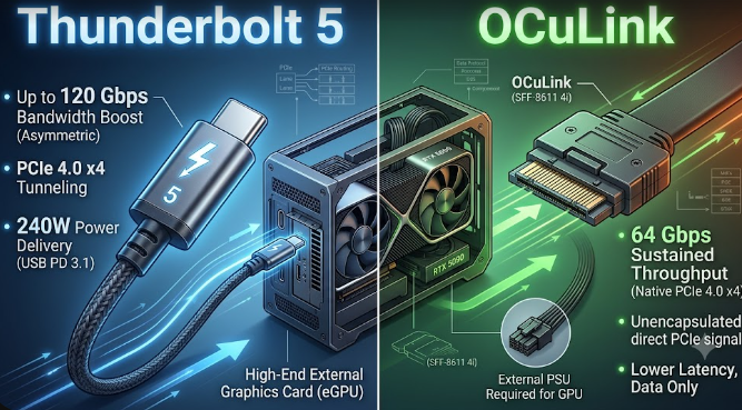
A comparison graphic showcasing OCuLink vs. Thunderbolt 5 connectors for an external graphics card setup.

Are you a handheld PC gamer wanting higher frame rates? Maybe you are a laptop power user or an AI developer running local Large Language Models (LLMs). In 2026, boosting your portable device with an external graphics card (eGPU) is easier than ever before. However, picking the right connection standard can feel overwhelming. Today, the ultimate hardware battle comes down to OCuLink vs. Thunderbolt 5. Both options promise massive speeds, but they achieve their performance goals in fundamentally different ways. Understanding these technical specifications will help you invest your money wisely.

Understanding OCuLink vs. Thunderbolt 5 Architecture

To grasp how these technologies differ, we must look at how they talk to your computer. OCuLink operates as a direct, un-tunneled PCIe 4.0 x4 connection. Consequently, it delivers a clean 64 Gbps stream of raw data straight to your processor. Think of OCuLink as an open, private highway where your graphics card drives directly to the CPU without stopping at any toll booths.

In contrast, Thunderbolt 5 acts as a complex protocol layer. This interface encapsulates the PCIe data alongside display and power signals to achieve its 80 Gbps bi-directional limit. Therefore, even though Thunderbolt 5 boasts a higher raw bandwidth number on paper, it introduces a controller “middleman” that must pack and unpack the data. This encapsulation creates protocol overhead, which can slow down real-world performance during intense tasks.

Real-World Latency and Stutter-Free Gaming

For passionate gamers, raw bandwidth numbers do not tell the whole story. Instead, frame stability and system response time dictate your actual experience. Because OCuLink completely lacks an extra protocol controller, it drastically reduces round-trip latency. Specifically, OCuLink keeps system latency under 25 milliseconds. This ultra-low latency provides a remarkably stable, stutter-free experience in ray-traced gaming compared to Thunderbolt setups.

Furthermore, heavy visual workloads like ray tracing force the GPU and CPU to communicate constantly. When you use Thunderbolt 5, the data packets must travel through the Intel controller chip. This extra step frequently introduces micro-stutters during heavy gaming sessions. For example, open-world games that stream assets on the fly will feel noticeably smoother on a direct OCuLink line because your system drops fewer frames.

Accelerating Local AI Inference Speeds

If you are an AI developer, interface speeds directly alter your workflow productivity. Running local Large Language Models demands rapid data transfers between your laptop’s RAM and the external VRAM. Fortunately, the raw connection of OCuLink shines brightest in this area. When you load heavy LLMs, such as a massive 70B parameter model, a raw OCuLink connection finishes the job much faster than competing protocols.

Additionally, OCuLink accelerates the critical “time to first token” generation phase. Thunderbolt 5 introduces roughly 110 milliseconds of round-trip controller overhead for every API call. In contrast, OCuLink bypasses this delay completely. Consequently, if you deploy agentic AI chains that fire dozens of short prompts in a sequence, OCuLink will save you several seconds per task.

The Hot-Swap and Power Delivery Trade-off

However, absolute performance requires a few daily lifestyle sacrifices. We must be entirely transparent about OCuLink’s primary limitation. Unlike the user-friendly Thunderbolt 5, OCuLink lacks seamless hot-swapping capabilities. This means you cannot simply unplug the cable when you want to take your laptop to another room. Instead, you must completely power down your handheld device or laptop before connecting or disconnecting the external GPU.

Furthermore, OCuLink does not offer reverse power delivery. While a single Thunderbolt 5 cable can send up to 240 watts of power to charge your laptop while receiving graphics data, OCuLink handles data exclusively. Therefore, you must plug a separate power brick into your machine. If you value a clean, single-cable docking station experience, Thunderbolt 5 remains the undisputed king of convenience.

Final Verdict on OCuLink vs. Thunderbolt 5

Ultimately, your choice depends on whether you value maximum frame rates or daily convenience. If you want a seamless plug-and-play setup that charges your laptop, choose Thunderbolt 5. However, if you want to extract every single ounce of performance for local AI development or high-end competitive gaming, OCuLink provides the best raw value in 2026. For further technical details on setting up external graphics enclosures and testing protocols, you can read more on the StorageReview Hardware Guides.

References

  • XDA Developers. (2026). “I expected Thunderbolt 5 to replace OCuLink for eGPU setups, but it didn’t.”
  • TechPowerUp. (2025). “External GPU Connection Battle: OCuLink Beats Thunderbolt 5 by About 16%.”
  • Local AI Master. (2026). “Thunderbolt vs OCuLink for eGPU AI: Real Benchmarks.”
  • Intel Corporation. (2025). “Thunderbolt 5 Technology for Next-Generation Gaming.”

How AMD 3D V-Cache Technology Uses Direct Cu-Cu Bonding

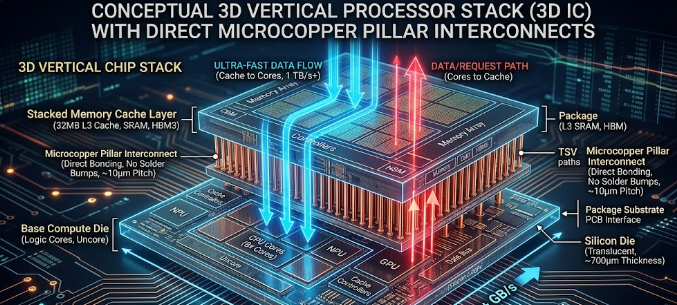
Technical diagram showing direct copper bonding inside a processor chip utilizing AMD 3D V-Cache technology.

Gamers and PC builders always want faster processors to run heavy workloads. To achieve this goal, AMD introduced an incredible hardware innovation known as AMD 3D V-Cache technology. Consequently, modern X3D processors deliver unmatched gaming performance by changing how engineers build CPUs. In this article, we will look at the physical hardware and advanced engineering driving this design.

Moving Upward with AMD 3D V-Cache Technology

Traditionally, chip makers expanded processor size horizontally across a flat plane. This older method represents planar expansion. However, spreading components out across a flat surface creates major problems. It increases the physical size of the chip and forces data to travel longer distances. As a result, latency increases and slows down communication between the core and memory.

To solve this issue, AMD chose a radical vertical approach. Instead of expanding outward, engineers stack a 64MB SRAM cache die directly on top of the CPU compute die (CCD). Therefore, the processor gains massive memory capacity without expanding its horizontal footprint. This vertical shift keeps data paths incredibly short, which slashes latency and speeds up performance dramatically.

The Power of Direct Cu-Cu Bonding Specs

Older chip designs connected stacked layers using tiny traditional solder bumps, which engineers call micro-bumps. Unfortunately, micro-bumps take up too much space and create high electrical resistance. They also limit how close connection points can be. To overcome this limitation, AMD uses a cutting-edge hybrid bonding process called direct copper-to-copper (Cu-Cu) bonding.

This new design completely eliminates traditional solder bumps. Instead, the copper pads of the top layer touch the copper pads of the bottom layer directly. This precise method allows for a sub-10 μm interconnect pitch, meaning the connection points sit incredibly close together. Ultimately, AMD 3D V-Cache technology benefits from drastically lowered electrical resistance and vastly superior power efficiency.

Vertical Data Highways in AMD 3D V-Cache Technology

How do the CPU cores talk to this newly stacked memory so quickly? The answer lies in Through-Silicon Vias, or TSVs. TSVs act as microscopic vertical data highways that drill straight through the silicon layers.

Because these pathways are so tiny and numerous, they provide massive data lanes. Therefore, the CPU cores can access the stacked L3 cache at over 2 TB/s of bandwidth. This extreme speed ensures that the processor never starves for data during heavy gaming or intense workloads.

Managing Heat in Advanced 3D Processors

Stacking silicon layers creates amazing performance, but it also creates severe thermal challenges. When you place a cache die directly over hot CPU cores, you trap heat underneath. Consequently, these X3D chips have stricter maximum temperature limits, which engineers call Tjmax, compared to standard 2D processors.

To protect the hardware, AMD applies lower voltage ceilings to these chips. Extreme overclockers must respect these boundaries because excessive voltage can permanently damage the bonded layers. Therefore, choosing a high-quality cooling system is absolutely vital if you want to get the most out of AMD 3D V-Cache technology.

The Future of Processor Design

In conclusion, AMD has revolutionized CPU architecture by building upward rather than outward. By combining direct Cu-Cu bonding with microscopic vertical data paths, they have rewritten the rules of gaming performance. If you want to dive deeper into the official hardware specifications, you can read more about CPU architectures on the AnandTech CPU Tech Section.

References

  • AMD. (2026). AMD 3D V-Cache™ Technology Drives Density and Energy Efficiency Leadership. AMD Tech Insights.
  • Avaq Semiconductor. (2026). AMD 3D V-Cache Technology Explained: A Breakthrough in 3D Chip Integration for HPC and Gaming.
  • Yole Group. (2022). AMD 3D V-Cache with TSMC SoIC 3D Packaging Teardown Report.

Why PCIe 6.0 Retimers in AI Data Fabrics Are Critical for Speed

A detailed hardware diagram showing PCIe 6.0 retimers in AI data fabrics restoring signal strength between processors.

Artificial intelligence (AI) models require massive amounts of data to train and run efficiently. Because of this demand, modern data centers must move information between processors and memory at lightning speeds. This is why engineers now use PCIe 6.0 retimers in AI data fabrics to maintain clear communication lines. Without these specialized chips, high-speed servers would simply fail to process complex AI workloads.

The Physics Problem: Signal Integrity Bottlenecks

The latest PCIe 6.0 standard is incredibly fast, reaching transfer speeds of 64 Gigatransfers per second (GT/s). However, running data at this extreme frequency creates a massive physics problem known as signal degradation. When data travels at these speeds over standard motherboard copper traces, the electrical signal weakens almost immediately.

Consequently, the data distorts before it even reaches its destination. Think of this problem like shouting down a very long, windy tunnel. By the time your voice reaches the other side, the wind has turned your words into muffled, useless noise.

How Retimers Fix the Signal Loss

To solve this physical limitation, hardware architects install chips called retimers along the data path. These chips act like intelligent radio repeaters. First, the retimer catches the fading, noisy data signal before it degrades completely. Next, it cleans up the electrical noise and rebuilds the data packet. Finally, it retransmits a perfect, brand-new signal to the next component.

Therefore, using PCIe 6.0 retimers in AI data fabrics ensures that data travels across longer distances inside the server without any corruption. They are absolutely essential for keeping the internal data highway flowing smoothly.

Why Low Latency Matters for PCIe 6.0 Retimers in AI Data Fabrics

Speed is not just about bandwidth; it is also about latency. When you pool expensive GPU resources together for AI workloads, even a microscopic delay can ruin performance. Because of this issue, new hardware like Microchip’s XpressConnect retimers achieves an ultra-low latency of under 12 nanoseconds.

In the world of AI training, every single nanosecond counts. If one GPU stalls while waiting for data from another chip, the entire system slows down. This delay creates a bottleneck that wastes expensive computing power and increases operational costs.

By keeping latency below 12 nanoseconds, PCIe 6.0 retimers in AI data fabrics eliminate these microscopic data stalls. As a result, massive clusters of GPUs can work together seamlessly as if they were a single, giant processor.

Memory Disaggregation Specs: CXL 3.1 to the Rescue

Another major breakthrough in modern data centers is the Compute Express Link (CXL) 3.1 protocol. Traditionally, each processor socket has a strict physical limit on how much RAM it can hold. CXL 3.1 changes this rule entirely by introducing a concept called memory disaggregation.

This specific protocol allows multiple servers or GPUs to share a single, massive pool of external RAM. Instead of being trapped inside one server socket, the memory sits in an external pool that any processor can access on demand.

However, to connect these massive memory pools to your GPUs, you need an incredibly reliable connection. This is exactly where PCIe 6.0 retimers in AI data fabrics become valuable. They ensure the CXL 3.1 signals remain crisp and fast over the longer cables required for shared memory hardware.

Conclusion

Building efficient AI systems requires both massive bandwidth and perfect signal control. By combining CXL 3.1 memory pools with high-speed PCIe connections, data centers can handle the toughest AI workloads. Ultimately, deploying PCIe 6.0 retimers in AI data fabrics solves the core physics and latency issues of modern computing. For further technical details on how these components integrate into data centers, you can read more on the PCI-SIG Official Website.

References

  • Compute Express Link Consortium. (2023). CXL 3.1 Specification Features and Advancements.
  • Microchip Technology Inc. (2024). XpressConnect Retimers for PCIe 6.0 and CXL 3.0 Ultra-Low Latency Solutions.
  • PCI-SIG. (2022). PCI Express Base Specification Revision 6.0.

Are 8000Hz Polling Rate Peripherals Worth It? MCU and CPU Guide

High-performance 8000Hz polling rate peripherals displayed next to a competitive esports gaming setup.

Competitive gamers always search for the fastest hardware to gain an advantage in esports. Recently, gaming brands started releasing 8000Hz polling rate peripherals, promising near-zero input latency. While these advanced mice and keyboards sound amazing on paper, they demand a massive amount of power from your computer. Consequently, you must understand the hidden hardware costs before upgrading your setup.

The Math Behind 8000Hz Polling Rate Peripherals

To understand this technology, we need to look at raw timing math. A standard gaming mouse usually operates at a 1000Hz polling rate. This means the mouse reports its position to your PC 1,000 times every second, which translates to once every 1 millisecond (ms).

In contrast, 8000Hz polling rate peripherals report data 8,000 times per second. Therefore, this rapid reporting slashes the update interval down to a microscopic 0.125ms.

1000Hz Polling Rate = 1 report every 1.0ms
8000Hz Polling Rate = 1 report every 0.125ms

This rapid reporting creates an incredibly dense stream of positional data. As a result, your cursor movements feel significantly smoother and more responsive on your screen. However, you will only notice this microscopic difference under very specific hardware conditions.

Why Monitor Refresh Rates Create a Visual Bottleneck

Many gamers buy 8000Hz polling rate peripherals expecting an instant visual upgrade. Unfortunately, your monitor can create a massive visual bottleneck that negates the benefits.

If you use a standard 60Hz monitor, your screen only updates 60 times a second, or once every 16.67ms. Even a standard 144Hz gaming monitor only updates every 6.94ms. Therefore, these slower monitors physically cannot display the extra positional updates that an 8K mouse sends every 0.125ms.

Spec-Matching Guide for High Refresh Displays

To actually see the benefits of this technology, you need an ultra-high refresh rate display. Specifically, displays pushing 360Hz, 480Hz, or higher are physically necessary to render the smoother tracking data.

Monitor Refresh RateTime Between Screen Frames8K Polling Updates Per Frame
60Hz16.67 ms~133 updates
144Hz6.94 ms~55 updates
240Hz4.17 ms~33 updates
360Hz2.78 ms~22 updates

For example, a 360Hz monitor updates its frame every 2.77ms. While it still cannot show every single one of the 8,000 updates, it matches the dense data stream much better than slower screens. Thus, upgrading your mouse without a high-end monitor completely wastes the hardware’s potential.

Internal MCU Constraints of 8000Hz Polling Rate Peripherals

Transmitting thousands of data packets every second requires serious processing power inside the device itself. Standard gaming mice use basic, low-power microcontrollers to handle data tracking.

Conversely, 8000Hz polling rate peripherals require dedicated, high-performance microcontrollers (MCUs). This advanced internal hardware must compress and process the intense data stream before sending it through the USB cable. As a result, these advanced devices often cost significantly more and consume far more battery power if they use a wireless connection.

CPU Overhead Penalties and Game Performance

The real hidden cost of 8000Hz polling rate peripherals falls directly on your computer’s processor. Your CPU must process all 8,000 incoming data packets every single second.

This heavy workload demands continuous, intense CPU cycles from the host PC. If you play demanding first-person shooters, your processor is already working incredibly hard to render the game frames. Consequently, the added tracking data can easily overload older or mid-range processors.

How System Overload Affects In-Game Framerates

When your processor struggles with the sudden flood of mouse data, you will experience performance issues. Many players notice sudden, jarring drops in their in-game framerates (FPS) whenever they move their mouse quickly.

Furthermore, this heavy CPU overhead can cause micro-stuttering, which completely ruins your aiming consistency. Therefore, a hardware upgrade meant to give you a competitive advantage might actually hurt your gameplay if your CPU cannot handle the stress.

Final Recommendations for Competitive Gamers

In conclusion, 8000Hz polling rate peripherals offer groundbreaking latency reduction on paper. However, you must ensure your entire system is ready for the upgrade before purchasing them.

You absolutely need a top-tier modern CPU and a monitor that pushes at least 360Hz to truly enjoy the smoother tracking. If you use older or mid-range hardware, sticking to a stable 1000Hz or 2000Hz rate will provide a much better, stutter-free gaming experience. For a deeper look at how input latency and peripheral refresh rates affect competitive gaming performance, you can read the comprehensive analysis on Blur Busters.

References

  • Razer Inc. (2023). “Razer HyperPolling Technology: True 8000Hz Polling Rate Whitepaper.”
  • Blur Busters. (2021). “The Amazing Benefits of High Polling Rates (1000Hz vs 8000Hz).”
  • RTINGS Hardware Reviews. (2024). “Mouse Polling Rate: Does It Matter For Gaming?”