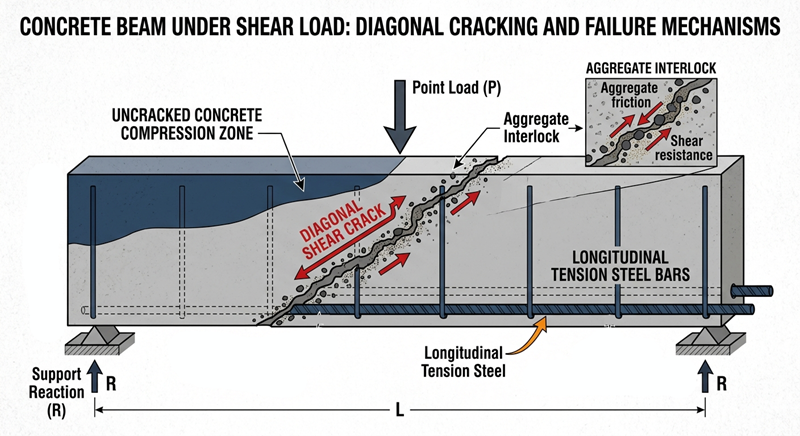
When designing concrete structural members, engineers must evaluate the unreinforced concrete shear capacity before deciding whether to add shear stirrups. Baseline shear capacity represents the inherent strength of a concrete beam or slab without shear reinforcement. Understanding this capacity prevents brittle shear failures and ensures economical design.
Core Mechanisms of Baseline Concrete Shear Resistance
Three internal physical mechanisms combine to provide baseline shear resistance in plain concrete:
- Uncracked Concrete Compression Zone: The solid flexural compression zone at the top of a beam directly resists a significant portion of vertical shear forces.
- Aggregate Interlock: Friction along the rough surfaces of a diagonal crack transfers shear stress across the opening.
- Dowel Action: The longitudinal steel tension bars resist vertical displacement across shear cracks like horizontal dowels.
Consequently, these three mechanisms work together to hold the beam intact until shear forces exceed the material limit.
Key Parameters Influencing Unreinforced Concrete Shear Capacity
Several structural variables directly control the shear strength of concrete without stirrups:
- Concrete Compressive Strength ($f_{ck}$ or $f_{cu}$): Higher concrete grades improve tensile strength, which directly enhances crack resistance and aggregate interlock.
- Longitudinal Tension Reinforcement Ratio ($\rho_l$): Increasing the main tension steel area ($A_{sl}$) improves dowel action. Additionally, more steel controls crack widths, preserving aggregate interlock. The ratio is expressed as:
$$\rho_l = \frac{A_{sl}}{b_w d}$$ - Scale Effect and Depth Factor ($k$): Deeper beams possess lower shear strength per unit area than shallow beams due to wider crack spacing. Therefore, design codes apply a depth scale factor ($k$) to account for this size effect:
$$k = 1 + \sqrt{\frac{200}{d}} \le 2.0$$
How Axial Loads Change Unreinforced Concrete Shear Capacity
Axial forces significantly alter how concrete resists shear stresses:
- Axial Compression: Compression forces (found in columns or prestressed beams) close diagonal cracks. As a result, compression increases aggregate interlock friction and significantly boosts shear capacity.
- Axial Tension: Tensile forces pull concrete cracks wider open. Consequently, axial tension drastically reduces aggregate interlock and lowers overall shear resistance.
Critical Design Checks: When Are Shear Links Required?
Engineers compare the applied ultimate shear force ($V_{Ed}$) against the design concrete shear resistance ($V_{Rd,c}$) to determine reinforcement requirements:
- $V_{Ed} \le 0.5 V_{Rd,c}$: The concrete alone safely handles the shear force. Therefore, you do not need shear stirrups (common in floor slabs).
- $0.5 V_{Rd,c} < V_{Ed} \le V_{Rd,c}$: Concrete provides enough strength, but codes require minimum (nominal) shear links to prevent sudden cracking.
- $V_{Ed} > V_{Rd,c}$: Plain concrete cannot carry the shear load alone. Therefore, you must design structural shear links ($A_{sw}/s$) to resist the full shear force.
BS 8110 vs Eurocode 2 Shear Evaluation Rules
Although both codes evaluate the same physical mechanisms, their mathematical approaches differ subtly:
- Material Strength Definitions: BS 8110 relies on concrete cube strength ($f_{cu}$), whereas Eurocode 2 uses cylinder strength ($f_{ck}$).
- Partial Safety Factors: BS 8110 applies a concrete material factor $\gamma_m = 1.25$ inside the shear equation. In contrast, Eurocode 2 uses $\gamma_c = 1.50$.
- Size Effect Treatment: Eurocode 2 uses an explicit equation for size effect ($k$), whereas BS 8110 uses tabular empirical values based on member depth ($d$).
Worked Example 1: BS 8110 Calculation
Consider a rectangular beam with width $b = 300\text{ mm}$, effective depth $d = 450\text{ mm}$, main tension steel $A_s = 942\text{ mm}^2$ (3H20), and concrete grade $f_{cu} = 30\text{ N/mm}^2$.
First, calculate the tension steel percentage:
$$\frac{100 A_s}{b d} = \frac{100 \times 942}{300 \times 450} = 0.698\%$$
Next, determine the design concrete shear stress ($v_c$) using the standard BS 8110 formula:
$$v_c = \frac{0.79}{1.25} \times \left( \frac{100 A_s}{b d} \right)^{1/3} \times \left( \frac{400}{d} \right)^{1/4} \times \left( \frac{f_{cu}}{25} \right)^{1/3}$$
Because $(400/450)^{1/4} = 0.971 < 1.0$, BS 8110 sets the minimum depth factor to $1.0$.
$$v_c = 0.632 \times (0.698)^{1/3} \times 1.0 \times \left( \frac{30}{25} \right)^{1/3}$$
$$v_c = 0.632 \times 0.887 \times 1.0 \times 1.063 = 0.596\text{ N/mm}^2$$
Finally, calculate total concrete shear capacity ($V_c$):
$$V_c = v_c \times b \times d = 0.596 \times 300 \times 450 = 80,460\text{ N} = 80.46\text{ kN}$$
Worked Example 2: Eurocode 2 Calculation
Let us evaluate the same beam dimensions using Eurocode 2 (BS EN 1992-1-1). Assume cylinder strength $f_{ck} = 25\text{ N/mm}^2$ (equivalent to $f_{cu} \approx 30\text{ N/mm}^2$).
First, calculate the reinforcement ratio ($\rho_l$):
$$\rho_l = \frac{942}{300 \times 450} = 0.00698 \le 0.02$$
Second, determine the depth scale factor ($k$):
$$k = 1 + \sqrt{\frac{200}{450}} = 1 + 0.667 = 1.667 \le 2.0$$
Third, compute shear strength parameter $C_{Rd,c}$:
$$C_{Rd,c} = \frac{0.18}{\gamma_c} = \frac{0.18}{1.5} = 0.12$$
Now, calculate the shear stress resistance ($v_{Rd,c}$):
$$v_{Rd,c} = C_{Rd,c} \times k \times \left( 100 \times \rho_l \times f_{ck} \right)^{1/3}$$
$$v_{Rd,c} = 0.12 \times 1.667 \times (100 \times 0.00698 \times 25)^{1/3}$$
$$v_{Rd,c} = 0.200 \times (17.45)^{1/3} = 0.200 \times 2.593 = 0.519\text{ N/mm}^2$$
Check the minimum shear strength limit ($v_{min}$):
$$v_{min} = 0.035 \times k^{3/2} \times f_{ck}^{1/2} = 0.035 \times (1.667)^{1.5} \times (25)^{0.5} = 0.377\text{ N/mm}^2$$
Since $0.519\text{ N/mm}^2 > 0.377\text{ N/mm}^2$, we use $0.519\text{ N/mm}^2$.
Finally, compute total unreinforced concrete shear capacity ($V_{Rd,c}$):
$$V_{Rd,c} = v_{Rd,c} \times b_w \times d = 0.519 \times 300 \times 450 = 70,065\text{ N} = 70.07\text{ kN}$$
Comparing Results and Practical Conclusions
Eurocode 2 yields a ultimate shear capacity of $70.07\text{ kN}$, whereas BS 8110 gives $80.46\text{ kN}$. Eurocode 2 produces a slightly more conservative result mainly because it uses a higher partial safety factor for concrete ($\gamma_c = 1.50$ vs $\gamma_m = 1.25$). For detailed structural standards and official design guidance on Eurocode 2 shear rules, visit The Concrete Centre for technical guides and design resources.
References
- British Standards Institution. (1997). BS 8110-1: Structural use of concrete – Code of practice for design and construction. BSI.
- European Committee for Standardization. (2004). Eurocode 2: Design of concrete structures – Part 1-1: General rules and rules for buildings (BS EN 1992-1-1). CEN.
- Mosley, W. H., Bungey, J. H., & Hulse, R. (2012). Reinforced Concrete Design to Eurocode 2 (7th ed.). Palgrave Macmillan.