What size rebar should be used for a residential slab? A Complete Guide

slab reinforcement in progress

If you plan to build a new house, you must make structural decisions early. Many builders and home owners frequently ask: what size rebar should be used for a residential slab? Selecting the right reinforcement ensures your building stands strong for decades. In residential construction, engineers use specific steel bars to handle everyday stresses. You cannot afford to guess these sizes because poor choices often lead to structural failure. In this guide, we will explore standard bar sizes, load differences, and why professional design software matters.

Understanding Loads: What size rebar should be used for a residential slab?

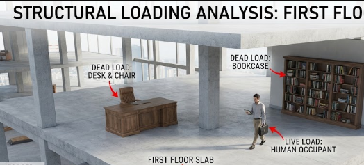
First, we must understand how slabs carry weight. Residential slabs handle much lighter dead and live loads compared to commercial buildings. Dead loads include the weight of the concrete itself, floor tiles, and permanent partition walls. Meanwhile, live loads represent the weight of people, furniture, and moving appliances.

Because homes experience lighter traffic than shopping malls, structural engineers specify smaller reinforcement bars. Consequently, understanding this fundamental load difference directly answers what size rebar should be used for a residential slab. You save money on steel while maintaining perfect structural integrity.

Standard High-Yield Steel Options

When engineers design a standard solid suspended slab for a home, they typically choose 10mm (Y10) and 12mm (Y12) high-yield steel bars. You will use these sizes for both the main and distribution reinforcement. For example, a common design might specify Y12 bars spaced at 200mm center-to-center for the main structural support.

Furthermore, builders often use Y10 bars for distribution to prevent temperature cracks and spread the load evenly. These high-yield steel bars provide excellent tensile strength. As a result, they prevent the concrete slab from bending and cracking under pressure.

Design Standards and Software Calculations

You should never rely on guesswork or rules of thumb when determining what size rebar should be used for a residential slab. Instead, you must derive the actual bar sizes and spacing from proper structural calculations.

Today, civil engineers use advanced structural design software like ProtaStructure or dedicated RCC11 spreadsheets to analyze the exact requirements. These tools follow strict building codes, such as BS 8110 or Eurocode 2, to calculate the precise steel area needed. Therefore, you should always hire a qualified professional to run these calculations for your specific project.

How Slab Thickness Influences Steel Area

Finally, the overall thickness of your suspended slab heavily influences the required steel area. Most residential suspended slabs range from 150mm to 175mm in thickness. A thicker slab offers more stiffness, but it also adds more dead weight to the structure.

As a result, the engineer must balance the concrete thickness with the right reinforcement size. If you increase the slab thickness, you might need to adjust the rebar spacing to meet code requirements. To learn more about standard concrete reinforcement practices and guidelines, you can read further on the American Concrete Institute (ACI) website.

References

  • British Standards Institution. (1997). BS 8110: Structural use of concrete.
  • European Committee for Standardization. (2004). Eurocode 2: Design of concrete structures.
Step-by-Step Guide to Calculating Steel Reinforcement in Concrete Slabs

When you design reinforced concrete structures, calculating steel reinforcement in concrete slabs remains a critical task. Concrete handles high compressive loads easily, but it struggles with tension forces. Therefore, civil engineers integrate steel bars to absorb tensile stresses. You must understand the core engineering principles and mathematical formulas to ensure your slabs remain safe and durable over time.

Estimating Bending Moments When Calculating Steel Reinforcement in Concrete Slabs

Before you compute any steel area, you must determine the bending moments acting on the slab. Engineers derive these bending moments from factored loads and effective spans. Specifically, dead loads and live loads combine to form ultimate design loads.

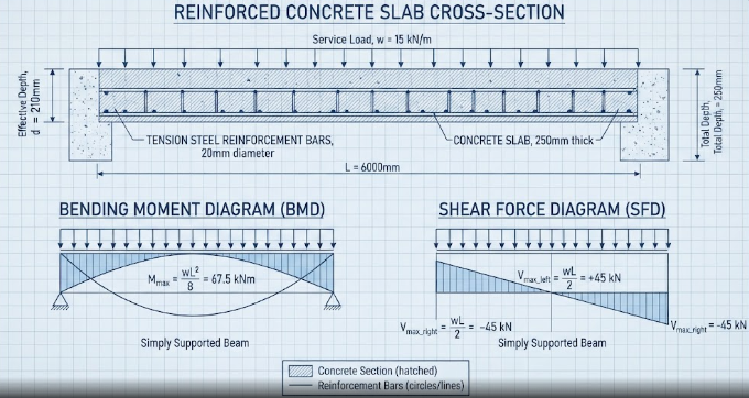
You can apply structural coefficients for continuous slabs or use classic bending moment formulas from structural analysis codes. For instance, a simply supported one-way slab uses the standard moment formula M = (w * l^2) / 8. Consequently, this value sets the foundation for your subsequent steel design calculations.

Determining the Required Area of Steel

After you establish the maximum bending moment, you can calculate the required cross-sectional area of tension reinforcement (As). This step links the ultimate bending moment directly with concrete compressive strength and steel yield strength. Modern design standards use a rectangular stress block to simplify this relationship.

For example, you apply the fundamental equation As = M / (0.87 * fy * z). In this equation, M represents the design bending moment, fy denotes the characteristic strength of the steel reinforcement, and z stands for the lever arm. Furthermore, you must verify that your calculated steel area meets minimum code requirements to prevent sudden brittle failures.

Bar Spacing and Selection Guidelines

Once you know the required steel area, you choose standard bar diameters and check clear spacing limits. Proper bar selection ensures your concrete consolidates fully around the reinforcement without honeycombing. Additionally, adequate spacing maintains strong bond strength between the steel and the surrounding concrete matrix.

You should select bar sizes that match your design calculations while keeping practical construction constraints in mind. For example, you might choose 12mm bars spaced at 150mm intervals. Moreover, always check that your chosen spacing does not exceed maximum limits specified by structural design codes, which usually restrict spacing to prevent wide surface cracks.

Conclusion and Further Engineering Practice

Mastering these foundational design steps allows you to approach any slab project with absolute confidence. By accurately estimating bending moments, calculating steel areas, and selecting proper bar spacings, you guarantee structural safety. To dive deeper into advanced structural design methodologies, you can explore detailed resources at The Structural Guide.

References

  • British Standards Institution. (1997). BS 8110-1: Structural use of concrete – Code of practice for design and construction. BSI London.
  • American Concrete Institute. (2014). Building Code Requirements for Structural Concrete (ACI 318-14). ACI Farmington Hills.
  • Mosley, W. H., Bungey, J. H., & Hulse, R. (2012). Reinforced Concrete Design to Eurocode 2. Palgrave Macmillan.

 Step-by-Step Guide to Determining Dead and Live Loads on Concrete Floor Slabs

dead and live load on reinforced concrete slab

When you design modern buildings, determining dead and live loads on concrete floor slabs remains an essential step for structural stability. You must accurately calculate these forces before any construction begins. Buildings experience various weights daily, and structural engineers must account for every single pound to prevent structural failures. Therefore, mastering this process protects both the building and its occupants.

Calculating Dead Loads When Determining Dead and Live Loads on Concrete Floor Slabs

Dead loads represent the permanent, static weights of the structure itself. Specifically, you compute the self-weight of the concrete slab by multiplying its density by its thickness (Self-weight = density * thickness). For instance, reinforced concrete typically weighs about twenty-four kilonewtons per cubic meter.

Additionally, you must add allowances for floor finishes, screed, tiles, ceilings, and internal partitions. These elements add fixed weight that remains constant throughout the entire lifespan of the building.

Selecting Live Loads While Determining Dead and Live Loads on Concrete Floor Slabs

Live loads change over time and depend heavily on how people use the building. Therefore, occupancy type dictates the minimum characteristic imposed loads based on standard building codes. For example, residential rooms require lower live load values than crowded office spaces or heavy storage areas.

You must check local building codes to find exact figures for your specific project. Consequently, proper live load selection ensures your floor handles daily human activity safely.

Applying Load Combinations for Ultimate Limit State

After you calculate individual loads, you must combine them safely using ultimate limit state factors. Ultimate limit state design ensures that structures withstand worst-case loading scenarios without collapsing. Engineers apply specific safety factors to both dead and live loads (Ultimate Load = (1.4 * Dead Load) + (1.6 * Live Load)).

For instance, a common combination multiplies dead loads by one point four and live loads by one point six. These safety margins account for unexpected overloads and material variations.

Solved Example: Calculating Slab Ultimate Load According to BS 8110

Let us examine a practical example to clarify these concepts. Suppose you want to design a concrete floor slab with a span of 5 meters and a thickness of 200mm (0.2 meters). The additional dead load from finishes is 1.2 kN/m², and the live load is 1.5 kN/m². Furthermore, the unit weight of reinforced concrete is 24 kN/m³.

First, you calculate the self-weight of the slab (Self-weight = 24 kN/m^3 * 0.2 m = 4.8 kN/m^2). Next, you find the total dead load by adding the self-weight and the additional dead load (Total Dead Load = 4.8 + 1.2 = 6.0 kN/m^2).

After that, you apply the BS 8110 safety factors for the ultimate limit state (Ultimate Load = (1.4 * 6.0) + (1.6 * 1.5)). Multiplying these values gives 8.4 + 2.4, resulting in an ultimate design load of 10.8 kN/m². Although the 5-meter span is not used directly in calculating the load per square meter, you will need it later when computing bending moments.

Mastering these foundational steps ensures your concrete floor slabs remain safe and reliable. You can easily protect your structures from unexpected failures by carefully calculating every load component. To explore more technical guides and civil engineering resources, you can visit the Civil Engineering Portal.

References

  • American Concrete Institute. (2014). Building Code Requirements for Structural Concrete (ACI 318-14). ACI Farmington Hills.
  • British Standards Institution. (1997). BS 8110-1: Structural use of concrete – Code of practice for design and construction. BSI London.

How to Calculate the Thickness of a Concrete Slab

structural drawing showing slab thickness

When you design floors or roofs, how to calculate the thickness of a concrete slab stands out as a critical task. Therefore, getting this dimension right ensures safety, structural integrity, and cost-effectiveness. Furthermore, an incorrect thickness leads to structural failure or unnecessary expenses. Consequently, every engineer must master the foundational rules governing slab design according to established codes like BS 8110.

Understanding Span-to-Depth Ratios

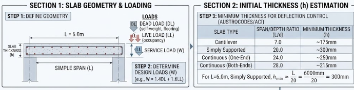
Standards like BS 8110 provide basic guidelines for how to calculate the thickness of a concrete slab. Specifically, structural engineers rely on span-to-effective-depth ratios. For instance, a simply supported slab requires a basic ratio of 20. When you apply a modification factor based on reinforcement stress, you adjust this baseline ratio to control deflection and prevent cracking.

Design Example: Step-by-Breast Calculation

Let us apply a practical example to demonstrate how to calculate the thickness of a concrete slab using BS 8110 guidelines. Assume you have a simply supported slab with a span of 5 m (5000 mm). The additional dead load is 1.2 kN/m2, and the live load is 1.5 kN/m2. Use an ultimate load combination of 1.4gk + 1.6qk, a concrete strength (fcu) of 25 N/mm2, steel yield strength (fy) of 460 N/mm2, a nominal cover of 20 mm, a reinforcement bar diameter of 12 mm, and a modification factor of 1.4.

Computing Effective Depth and Total Thickness

First, determine the allowable span-to-effective-depth ratio by multiplying the basic ratio by the modification factor: 20 x 1.4 = 28.

Next, calculate the required effective depth (d) by dividing the clear span by the allowable ratio: d = 5000 mm / 28 = 178.57 mm.

Finally, find the total slab thickness (h) by adding the effective depth, the nominal cover, and half of the reinforcement bar diameter: h = 178.57 mm + 20 mm + (12 mm / 2) = 204.57 mm. You can round this value up to 210 mm for practical site construction.

Load and Deflection Considerations

Anticipated loads play a massive role in determining structural dimensions. Specifically, you must account for dead loads, such as self-weight, and live loads like furniture and people. Furthermore, ultimate load combinations govern the ultimate limit state checks. If a slab is too thin, it will deflect excessively under heavy service loads. Therefore, engineers calculate deflections carefully to satisfy serviceability requirements.

Durability and Fire Ratings

Structural safety goes beyond simple load-bearing capacity. Environmental exposure classes and fire resistance requirements often force engineers to increase nominal slab thickness. For example, a slab exposed to moisture needs extra concrete cover to protect internal steel reinforcement from corrosion. Additionally, building codes mandate specific minimum thicknesses to achieve required fire resistance ratings. Therefore, even if a thin slab satisfies basic span-to-depth ratios, you must check durability rules.

Conclusion

Mastering how to calculate the thickness of a concrete slab protects buildings from premature failure and costly repairs. By carefully combining span-to-depth ratios, load analysis, and durability codes, you produce safe, reliable structures. For more deep dives into structural design principles, check out The Concrete Society for further reading.

References

  • British Standards Institution. BS 8110-1: Structural use of concrete – Code of practice for design and construction.
  • Mosley, W., Bungey, J., & Hulse, R. (2012). Reinforced Concrete Design. Palgrave Macmillan.

Main Reinforcement vs Distribution Reinforcement in Slab Design

reinforced concrete slanb under construction

When you design concrete floor systems, understanding main reinforcement vs distribution reinforcement is crucial for structural integrity. Concrete handles compression well, but it cracks easily under tension. Therefore, structural engineers place steel bars inside the concrete to carry these tensile loads. However, not all steel bars perform the same function. You must use different types of reinforcement to handle various stresses safely.

Understanding Main Reinforcement vs Distribution Reinforcement in Slabs

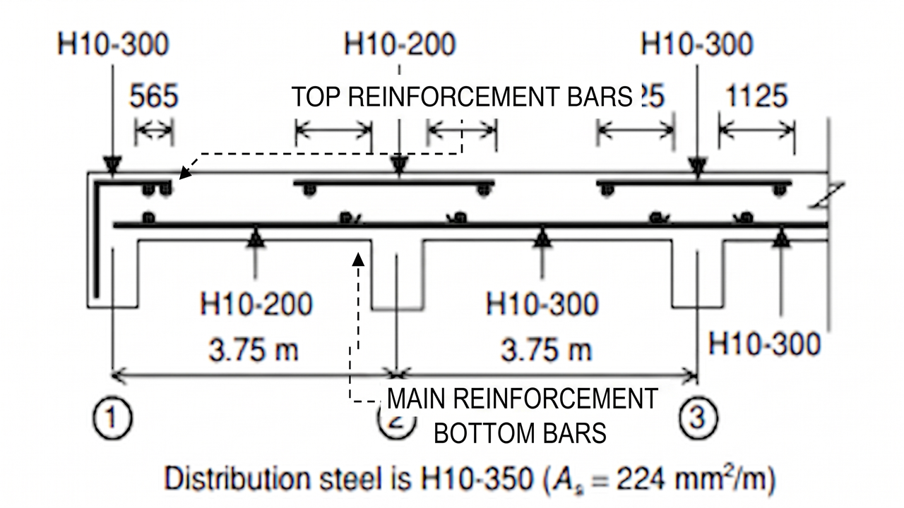
The main reinforcement plays the most important structural role in any slab design. Specifically, these primary bars run parallel to the direction of the main bending moment. When loads push down on a slab, the bottom fibers stretch and experience heavy tensile stress.

Consequently, main reinforcement bars absorb these principal tensile stresses and prevent the concrete from cracking or failing. For example, in a simply supported one-way slab, you place the main bars running across the shorter span where bending moments reach their peak. You calculate the exact size and spacing of these bars based on maximum design bending moments.

The Role of Distribution Reinforcement

While main bars handle primary bending, secondary bars manage other critical forces. Distribution reinforcement runs perpendicular to the main reinforcement across the slab. This secondary steel grid serves several vital purposes in structural engineering.

First, it handles transverse stresses that develop across the slab. Second, it helps distribute concentrated or point loads evenly across a wider area. Third, distribution bars resist thermal movements and shrinkage cracking as the concrete cures and hardens over time. For instance, when hot weather causes concrete to shrink, these perpendicular bars hold the matrix together and minimize surface cracking.

Placement Rules and Structural Positioning

Proper placement of your steel bars directly impacts the load-bearing capacity of your slab. Therefore, you must follow strict positioning rules when laying out your structural grid. In a single-layer or multi-layer mesh, you place the main reinforcement outermost to maximize the effective depth of the slab.

The effective depth represents the distance from the extreme compression fiber to the centroid of the tension steel. Placing main bars closer to the outer tension face increases their leverage against bending moments. Meanwhile, you position the distribution reinforcement directly on top of or tied inside the main bars. This arrangement locks the entire steel skeleton in place before you pour fresh concrete.

Conclusion

Mastering the balance between primary and secondary steel bars ensures your concrete structures remain safe and durable. By understanding the distinct functions of each steel layer, you can design slabs that resist bending, control cracks, and handle heavy loads efficiently. To explore more construction tutorials and general engineering insights, you can visit Specs Finder.

References

  • British Standards Institution. (1997). BS 8110-1: Structural use of concrete – Code of practice for design and construction. BSI London.
  • American Concrete Institute. (2014). Building Code Requirements for Structural Concrete (ACI 318-14). ACI Farmington Hills.
  • Mosley, W. H., Bungey, J. H., & Hulse, R. (2012). Reinforced Concrete Design to Eurocode 2. Palgrave Macmillan.

Understanding Reinforced Concrete Slabs: Definition, Components, and Applications

 A detailed cross-section diagram highlighting understanding reinforced concrete slabs with steel reinforcement bars.

Are you curious about how modern buildings stay strong and stable? Understanding reinforced concrete slabs is essential because these horizontal structural elements form the floors and roofs we use every day. Without them, multi-story buildings and safe roofing systems would not exist in modern construction. Builders rely on these components to create flat, sturdy surfaces that support heavy loads safely.

What is a Structural Slab?

A structural slab is a flat, horizontal surface element typically used for floors, roofs, and foundations in buildings. Engineers design these vital elements to transfer loads securely to beams, columns, and walls. You can find them in almost every residential house, commercial skyscraper, and industrial warehouse. They provide a safe platform for people, furniture, and equipment while dividing a building into usable vertical levels.

How Composite Action Works

Understanding reinforced concrete slabs requires looking closely at how two different materials work together. Concrete handles high compressive forces exceptionally well, but it is weak when pulled or stretched. Steel reinforcement bars, placed inside the concrete, handle tensile stresses with ease. This combination is known as composite action. Together, the concrete and steel create a powerful structural material that resists both crushing and bending forces.

Common Applications in Construction

Builders use these versatile elements in many different areas of residential and commercial projects. For example, ground-supported slabs rest directly on compacted soil, which makes them ideal for warehouses and ground floors. Suspended floors span across open spaces between beams and columns in multi-story buildings. Furthermore, roof decks protect top-floor rooms from weather elements while providing a solid base for waterproofing and insulation layers.

Key Benefits of Reinforced Concrete Slabs

Buildings need strong materials to last for decades without failing. Understanding reinforced concrete slabs helps you appreciate their incredible durability against heavy weights and harsh weather. Furthermore, they offer excellent fire resistance, which keeps occupants safe during emergencies. These slabs also provide good acoustic insulation to block noise between floors, and their high rigidity prevents excessive shaking or bending under everyday loads.

Conclusion and Further Reading

In summary, these structural elements play a vital role in modern architecture and civil engineering. By combining the compressive strength of concrete with the tensile strength of steel, builders create safe, durable, and reliable horizontal surfaces. If you want to explore more about structural design standards and advanced building materials, you can check out detailed guides on The Constructor.

References

  • Nilson, A. H., Darwin, D., & Dolan, C. W. (2010). Design of Concrete Structures. McGraw-Hill Education.
  • Reynolds, C. E., & Steedman, J. C. (2008). Reinforced Concrete Designer’s Handbook. Taylor & Francis.