When you shop for Aluminum roofing sheets yon may be asked what thickness do you want?. Generally thicker aluminum roofing sheets costs more because they are much more durable. if your roof span is longer than 10m for instance, you may be required not to buy less than a certain thickness of roofing sheet.
Below are some required factors to consider when choosing a certain thickness of aluminum roofing sheets for your roofing project.
Durability: Thicker sheets are generally more durable and resistant to damage from environmental factors like hail, heavy rain, and wind. They can also resist denting better than thinner sheets.
Load-Bearing Capacity: The thickness affects the roofing sheet’s ability to bear weight, such as in heavy snowfall areas. Thicker sheets can handle greater snow loads without deformation.
Longevity: Thicker sheets tend to have a longer lifespan as they are less susceptible to corrosion and wear over time.Insulation: Thicker sheets may offer better insulation properties, helping to regulate temperature within the building.When it’s important:
Climate: In areas with extreme weather conditions, like frequent storms or heavy snow, thicker roofing sheets are crucial for durability and safety.
Building Use: The thickness depends on the intended use of the building. Commercial or industrial structures may require thicker sheets to handle equipment loads.
Budget: Thicker sheets are usually more expensive. Balancing your budget with your roofing needs is essential.Aesthetics: Thicker sheets can have a different appearance, which might be important for architectural or aesthetic reasons.I
The thickness of aluminum roofing sheets is vital for ensuring structural integrity, longevity, and performance, and it should be chosen based on the specific requirements of your location and building type.
CommonThickness of Aluminium Roofing Sheets
The common thickness of aluminum roofing sheets suitable for roofing buildings typically ranges from 0.5mm to 1.2mm. Here’s a rough guideline for common applications:
0.5mm to 0.7mm: These thinner sheets are often used for residential roofing in areas with mild weather conditions. They are cost-effective and suitable for most homes.
0.8mm to 1.0mm: These mid-range thicknesses offer better durability and can handle moderate weather conditions. They are commonly used for both residential and commercial roofing.
1.0mm to 1.2mm: Thicker sheets in this range are suitable for commercial and industrial buildings or in areas prone to extreme weather, such as heavy snowfall or hail.
The choice of thickness should consider factors like local climate, budget, and the specific requirements of the building. It’s also essential to consult with roofing professionals to determine the most appropriate thickness for your roofing project.
Is 0.4mm or 0.45mm aluminum roofing sheet good for roofing?
A 0.45mm or 0.4mm thick aluminum roofing sheet can be suitable for roofing depending on specific factors such as:
Climate: In regions with mild weather conditions and minimal exposure to extreme elements like heavy rain, snow, or hail, thinner sheets may suffice.
Building Type: For residential structures with standard roofing needs, thinner sheets can work well. However, for commercial or industrial buildings with larger roof spans, thicker sheets may be preferable for added durability.
Budget: Thinner sheets are often more cost-effective, making them an attractive choice if you’re working with a limited budget.
Maintenance: Thicker sheets typically require less maintenance over time, so consider how much upkeep you’re willing to invest in. Local Codes and Regulations: Check if there are any local building codes or regulations that specify minimum thickness requirements for roofing materials .It’s essential to assess your specific roofing requirements and the climate in your area to determine if 0.45mm or 0.4mm thick aluminum roofing sheets are adequate. Consulting with a roofing professional or manufacturer can also provide valuable guidance based on your individual circumstances.
Long Span Aluminum roofing sheets are a popular roofing material known for their durability, lightweight nature, and versatility.
Notable Properties of Long-Span Aluminum Roofing Sheets
Material: They are primarily made of aluminum, which is a lightweight and corrosion-resistant metal.Design: Long-span roofing sheets are typically designed for wide coverage, reducing the number of seams and joints on a roof. This design enhances their structural integrity and makes them suitable for spanning long distances without additional support.
Durability: Aluminum is highly resistant to corrosion and rust, making these roofing sheets ideal for areas with high humidity or proximity to the sea. They have a long lifespan and require minimal maintenance.
Lightweight: Aluminum is one of the lightest roofing materials available, making installation easier and reducing the structural load on the building.
Variety: They come in various profiles and designs, allowing homeowners and builders to choose from a range of aesthetic options.
Color Options: Aluminum long-span roofing sheets are often available in a variety of colors and finishes, allowing for customization to match the overall design and style of the building.
Energy Efficiency: They can reflect sunlight, helping to reduce indoor temperatures and improve energy efficiency in hot climates.Cost: While aluminum roofing sheets can be more expensive upfront compared to some other roofing materials, their durability and long lifespan often make them cost-effective in the long run.
Installation: Proper installation is essential to ensure they perform as intended. They should be installed by experienced professionals to avoid issues like leaks or damage.
Maintenance: Aluminum roofing requires minimal maintenance. Occasional cleaning and inspection for loose fasteners or damaged sections are typically all that’s needed.
Environmental Benefits: Aluminum is a recyclable material, so these roofing sheets can be recycled at the end of their lifespan, contributing to sustainability efforts.Weather
Resistance: They are known for their ability to withstand harsh weather conditions, including heavy rain, wind, and even hail.
Noise Reduction: Aluminum roofing sheets can help reduce noise from rain and other external sources.Fire Resistance: Aluminum is non-combustible, adding an extra layer of fire protection to your home or building.
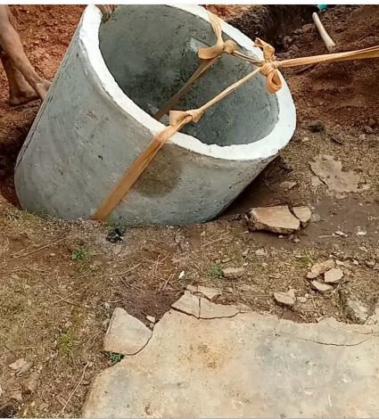
Constructing a septic tank using concrete rings is a common method. Here are general steps to guide you, but it’s crucial to consult local regulations and consider hiring a professional for proper design and installation:
Materials and Tools Needed:
– Concrete rings (precast or poured on-site)
– Sand or gravel
– Reinforcement bars (rebar)
– Concrete mix
– Shovel
– Level
– String line
– Tape measure
– PVC pipes (inlet and outlet)
– Manhole cover
Steps:
1. **Permit and Design**: Obtain the necessary permits and design your septic tank based on the size and capacity needed for your household. Comply with local regulations.
2. **Excavation**: Dig a hole in the ground to the required depth and dimensions for your septic tank. Ensure it’s level and well-compacted at the bottom.
3. **Base Preparation**: Add a layer of sand or gravel to the bottom of the excavation to create a stable base for the concrete rings.
4. **Laying the Rings**: Place the first concrete ring at the bottom of the hole. Make sure it’s level and properly aligned. Add subsequent rings on top, making sure they interlock securely. Use rebar to reinforce the joints between rings.
5. **Inlet and Outlet Pipes**: Install PVC pipes for the inlet and outlet. The inlet pipe carries wastewater from your home to the tank, while the outlet pipe directs treated effluent to the drain field. Ensure proper slope for drainage.
6. **Baffles**: Inside the tank, install concrete baffles to separate the incoming sewage from the effluent. This helps with settling and treatment.
7. **Manhole**: Create a manhole for access to the tank. This should have a secure cover for inspection and maintenance.
8. **Concrete Pouring**: Fill the gaps between the rings with concrete mix, making sure it’s properly compacted and reinforced with rebar.
9. **Curing**: Allow the concrete to cure for the recommended time, typically several days, to achieve full strength.
10. **Inspection and Testing**: After curing, inspect the tank to ensure there are no leaks or structural issues. Perform a hydraulic load test to ensure it functions correctly.
11. **Backfilling**: Carefully backfill around the tank with soil, ensuring it’s well-compacted to prevent settling.
12. **Final Inspection**: Have your septic tank system inspected and approved by the local authorities or a septic system professional.
13. **Maintenance**: Regularly maintain and pump your septic tank as per local guidelines to prevent blockages and ensure proper functioning.
Remember that septic tank installation can have environmental and health implications, so it’s crucial to follow local regulations and guidelines. Consulting with a professional septic system installer is advisable for a safe and compliant installation.
General procedure for design of solid slabs to BS Code.
1.Determine a suitable slab depth; you can easily estimate this by using the formula stated below;
Effective depth = span/( basic ratio × modification factor)
Span/effective depth ratios
For a simply supported design, the basic ratio is = 20 ( table 3.9, page 35 of BS 8110 part 1 : 1997). Use an initial modification factor (m.f) of 1.4.
Also the architect/ engineer may specify the slab thickness for you.
However, your slab design must satisfy deflection requirements otherwise you will have to redesign.
Ways to make your design slab satisfy deflection requirements if failed initially is to either increase slab thickness or amount of reinforcement or both.
2. Calculate the main and secondary reinforcement areas; you can do this by using the formulas stated in the BS code. ( Details later)
3. Check for excessive deflection ; as stated earlier in number 1, your design must satisfy deflection requirements.
4. Detailing requirements; the economical arrangement of steel reinforcement. You can refer to clause 3.12.10.3, BS 8110. An explanatory diagram is shown below for a simply supported case.
Detailing requirements for simply supported (a) & continuous ( b) slabs
It means that 40% of the reinforcement placed around the center of the slab ( which is critical) only, should extend to the edges of the slab ( which is less critical).
Explanation of other important points in solid slab design to BS 8110
Effective span of slab:
Referring to the diagram above, the effective span of slab refers to ‘A’ the distance between the centers of bearings, or the clear distance between supports ‘D’, plus effective depth of slab ‘d’.
Calculating steel areas.
In calculating the slab self weight, the overall depth of the slab referred to as ‘h’, should be used. h is the effective depth of slab plus allowance for cover to reinforcement plus half the assumed main steel diameter bar.
The self weight of the slab together with the dead and live load is used to determine the design moment ‘M’.
The value of M must be checked against the value of Mú which is the ultimate moment of resistance
Mú = 0.156fcubd²
Where b=1000mm and fcu = strength of concrete.
If Mú ≥ M then the slab doesn’t need compression reinforcement which is usually the case.
Main reinforcement steel areas
The area of reinforcement Aₛ can be determined using Aₛ= M÷(0.87𝑓yz) where,
M = design moment= WL²/8 (for simply supported slab)
W = design load of slab in kN/m²
L = span of slab in meters.
𝑓y= strength of steel
z = d[0.5 + √ (0.25 – K/0.9)] and
K= M / fcubd²
Secondary reinforcement steel areas
Secondary reinforcement also refers to distribution steel. As per BS 8110, it is calculated as follows;
Aₛ min = 0.24% Ac when 𝑓y = 250N/mm²
Aₛ min = 0.13% Ac when 𝑓y = 460N/mm²
Check that your slab design meets deflection requirements
Design service stress, fs = (2 𝑓y Asreq.) ÷ ( (3 Asprov), (table 3.10 page 36 of BS 8110 part 1 1997.)
Where Asreq & Asprov is the area of steel calculated and the area of steel provided, respectively.
Modification factor;
m.f = 0.55 + (477 – fs) ÷[120 ( 0.9 + M/bd²)] ≤ 2
Now this m.f is your actual m.f since it is a function of the area of steel calculated and area of steel provided.
Use this new m.f to replace the m.f you initially assumed to be 1.4 in the equation;
Effective depth; d = span/( basic ratio × modification factor).
you can also determine m.f from the table below
If the assumed value of d is greater than actual d, then deflection requirements are satisfied.
Crack widths
The BS code specifies that crack width should not exceed 0.3mm. except by calculation, the following rules should ensure crack width requirements are satisfied;
fy = 250N/mm² and depth of slab ≤ 250mm
or
fy = 460N/mm² and depth of slab ≤ 200mm
or
the percentage of reinforcement ( 100As/bd) ≤ 0.3%
Maximum bar spacing of reinforcement
BS code specifies that the clear distance between tension bars should be less than 3d or 750mm whichever is the lesser.
Example design of a simply supported solid slab
From the diagram of part of a floor plan shown above, I will be designing the panel labeled A.
The first thing to check is if the slab is a one or two way slab. By observing the dimensions relating to the slab panel, the longer side is
3401 + 587 + 1225 = 5213mm
The shorter side of the panel is
1150 + 1225 = 2375mm
Therefore longer side ÷ shorter side =
5213÷2375= 2.19 ≥ 2;
Panel A is a one way slab.
This means that the main reinforcement bars will span along the y- axis ( shorter side) and the distribution bar will span along the x – axis ( longer side).
direction of main reinforcement
Note that in a one way slab, the span of the slab is the shorter side. The span of the slab panel A being designed is 2375mm.
Further observation of the slab panel will show that its thickness (overall depth of slab) has been given as 150mm;
h = 150mm
Your duty as the designer is to calculate the required steel reinforcement and check if the design satisfies deflection requirements. If the slab thickness wasn’t given then you are free to assume a thickness and then check that it works.
Calculating the Design load.
The formula stated by BS code is
1.4Gk + 1.6Qk
where Gk = dead load
Qk = live load
dead load is the self weight of the slab plus finishes
Live load refers to variable or movable loads such as people, furniture etc, the slab carries. Live loads for different categories of buildings are stated in BS 6399 part 1: 1997.
Gk = weight of concrete x slab thickness
= 24kN/m³ x 0.15m ( slab thickness of 150mm)
= 3.6kN/m², plus finishes of say 1.2 kN/m² which gives a total gk of
4.8kN/m² ;
Gk = 4.8kN/m²
For private dwellings, Qk = 1.5kN/m² (see table 1 of BS 6399 part 1: 1997)
Design load = 1.4gk + 1.6qk
=( 1.4x 4.8 + 1.6 x 1.5) kN/m²
= 9.12kN/m² per m width ( slabs are designed per m width.)
Design moment M = WL²/8
where W = design load and L = span of slab
W=[ 9.12kN/m² x ( 2.375m)² ] / 8
= 6.43kNm
ultimate moment of resistance
Mu= 0.156fcubd²
Now d = effective depth of slab which can be estimated as overall depth of slab minus concrete cover to reinforcement minus half of main steel diameter
I.e. d = 150mm – 25mm – 6mm = 119mm.
( 25mm is concrete cover to reinforcement and 6mm is half the diameter of 12mm steel rod)
b = 1000mm ( slabs are designed per m width)
fcu = 25N/mm² ( strength of concrete)
Mu = 0.156 x 25N/mm² x 1000mm x (119mm)² = 55.2279 x 10⁶ Nmm
= 55.23kNm
Since M < Mu no compression reinforcement is required.
K= M / fcubd²
= 6.43 x 10⁶/ ( 25 x 1000 x 119²)
0.0182
z = d[0.5 + √ (0.25 – K/0.9)]
= 119[ 0.5 + ✓ ( 0.25 – 0.0182/0.9)]
= 116.54mm ≤ 0.95d
Limiting to 0.95d
0.95d = 113.05; use z= 113.05
Hence,
Aₛ= M÷(0.87fyz)
= 6.43 x 10⁶ ÷ ( 0.87 x 460 x 113.05)
Aₛ required. = 142.12 mm²/m width of slab
From fig. 1 shown above, use Y10 bars at 200mm spacings as main steel reinforcement
I.e.
Y10- 200
Aₛ provided = 393 mm²/m
Distribution reinforcement
Minimum Steel reinforcement specified by code = 0.13%bh
= 0.13% x 1000 x 150
Aₛ minimum required.= 195 mm²/m
With reference to fig 1, use Y10 – 250 bars. Aₛ = 314mm²/m
Note that the calculated required reinforcement is less than the minimum reinforcement specified by code, in this case the minimum reinforcement specified by code supersedes and should be used to select provided steel. Also using Y10- 200 as main and distribution steel is OK. It’s your design, you are in charge, just make sure you follow the code requirements and design laying emphasis on economy.
Checks
Deflectioncheck
Design service stress,
fs = 2 fy As req./ (3 As prov)
= 2×460×142.12÷(3×393)
=110.9N/mm²
fs = 110.9N/mm²
m.f = 0.55 + (477 – fs) ÷[120 ( 0.9 + M/bd²)] ≤ 2
= 0.55 + (477- 110.9)÷[120(0.9 + (6.43 x 10⁶/100 x119²)]
=2.80 ≤ 2
Since m.f is limited to 2,
Hence, m.f = 2
dmin = span / basic ratio x m.f
= 2375mm / (20 x 2)
= 59.375mm
59.375mm ≤ 119mm hence deflection is satisfied.
Crack width check
Since the slab is less than or equal to 200mm thick, crack width check is satisfied
Maximum spacing check
The reinforcement spacing of 200mm for main steel and 250 mm for distribution steel is less than 3d ( 3 x 119 = 357mm) hence maximum spacing check is satisfied.
People dig wells to serve as an independent water supply system. These days before a well is dug, a survey is carried out on the site to determine the amount of water beneath the ground, its location, and yielding capacity. This will determine the type of well to be dug.
Types of wells
Generally wells can be categorized into 2 types;
Deep well and shallow well.
Deep well.
From an economical point of view,A well is considered deep when the length of the well is over 25ft or 7.62m deep. What causes the digging or boring of a deep well is as a result of the water table being too far from the top soil. Another reason for a deep well is if although, the water table is not far from the top soil, the soil beneath the water table doesn’t yield water, then the well has to be dug further down to locate the water yielding soil. Types of soil that hold and yield water are those of sand or rock formations. A type of soil that holds water but doesn’t yield it is a soil that consists mostly of shale.
Another definition of deep well is a well that extends several meters below the water table. Meaning that its source of water is not from the water table but from other water bearing stratum beneath the water table.
A deep well can extend up to 300m.
Shallow well
A well is considered shallow if the length is less than 25ft from the surface. This is because the water table is not too far from the surface and the soil directly under the water table yields water.
Shallow wells are also referred to as water table wells. Meaning, the source of water for these types of well is the water table. It also implies that if the water table is further down the earth ( over 25ft), the shallow well extends about the same length or more. Based on the location of water table, shallow wells can be over 35m in extreme cases.
Types of constructed wells
Generally they are of 3 types;
Dug well.
Driven well.
Bored well.
Hand Dug well.
A dug well is done using hand tools. A pick and shovel to dig the shaft, and a bucket and rope to lift out soil. This type of well cannot be dug a few feet below the water table. If the water table is very far from the surface ( over 10m deep),then a hand dug well may not be economically and practically viable. Most hand dug wells for private dwellings are less than 10m deep. Hand Dug wells are always shallow wells and they are the least costly.
Driven well
A driven well consists of pipes driven into the ground. The drive point is usually twisted into the ground by hand or powered auger. This type of well is suitable for Sandy soils and cannot be dug through rock formations. The well can be driven up to 100m. It can be shallow or deep,depending on the nature of the soil and water yielding characteristics.
Bored or drilled well
This type of well is also called bore hole. It also consists of pipes much larger than that used in a driven well, bored into the ground using a heavy drilling machine. Bore holes can reach depths of up to 300m and can be drilled through rocky formations. Boreholes can either be shallow or deep, depending on depth of water table and water yielding characteristics of the soil. It is the most expensive of the types mentioned in this article.
Reinforced concrete slabs can be divided into 2 types. They are In situ and precast slab. Insitu means a slab cast in place. Precast means that the slab is produced somewhere else and then transported to site for installation.
Cast in place slabs are further divided into 3 types. They are solid slab, flat slab and ribbed slab.
Solid slabs refers to slabs supported by beams or walls. They are economical up to spans of 5m
Flat slab refers to a slab supported by columns only. The main advantage flat slabs have over solid slabs is that they are easier to construct. Also, widows can extend to the underside of a flat slab since it doesn’t require beams for support. The main disadvantage for these types of slab is that they are prone to punching shear. Flat slabs are economical for spans ranging from 5m to 9m.
Ribbed slabs are Slabs in which part of the slab in the tension zone has been omitted thereby reducing its weight considerably. They have higher formwork costs compared to other slab systems.Ribbed slabs are economical for spans ranging from 8m – 12m.